

AI and IoT Insights
Practical articles on IoT platforms, edge gateways, embedded software, AI workflows, industrial protocols, smart hardware, and connected-product decisions.
Blog articles · Page 9
RTSP vs WebRTC: Choosing the Best Protocol for AI Video Recognition in IoT Systems
RTSP vs WebRTC for AI video recognition in IoT systems. Learn their key differences, latency, and best use cases in edge AI and real-time visualization.
From Wake Word Detection to Edge Intelligence: The Technical Potential of ESP32-S3 TensorFlow Lite Micro
Learn how ESP32-S3 TensorFlow Lite Micro enables edge AI and wake word detection with on-device inference for embedded and IoT devices.
Object Recognition Camera for AI Inventory Management: How ZedWMS’s AI Warehouse Management System Automates Operations
AI warehouse management system with object recognition camera. Automate inventory tracking, achieve 99% accuracy, reduce labor 40%. Real case studies inside.
What Is the Tuya Smart App and How It Powers Smart Devices
Learn what the Tuya Smart App is, how it connects IoT devices, and how businesses can customize it using the Tuya SDK for branded smart solutions.
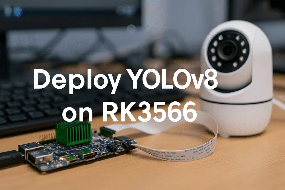
How to Deploy YOLOv8 on RK3566: Build Efficient Edge AI Inference from Scratch
Learn how to deploy YOLOv8 on RK3566 step by step. This complete edge inference tutorial covers model conversion, optimization, and real-time detection setup for embed...
Tuya Module Selection and Hardware Development Guide: WiFi, BLE, and Zigbee Comparison
Learn Tuya module selection and hardware development for WiFi, BLE, and Zigbee IoT modules. Build smarter hardware with the right Tuya solution.
Tuya SDK App Migration Guide 2025: How to Move from Tuya OEM App to a Custom SDK App
Migrate from Tuya OEM App to a Custom Tuya SDK App. Compare OEM limitations and pricing, explore SDK benefits, and follow our step-by-step migration guide.
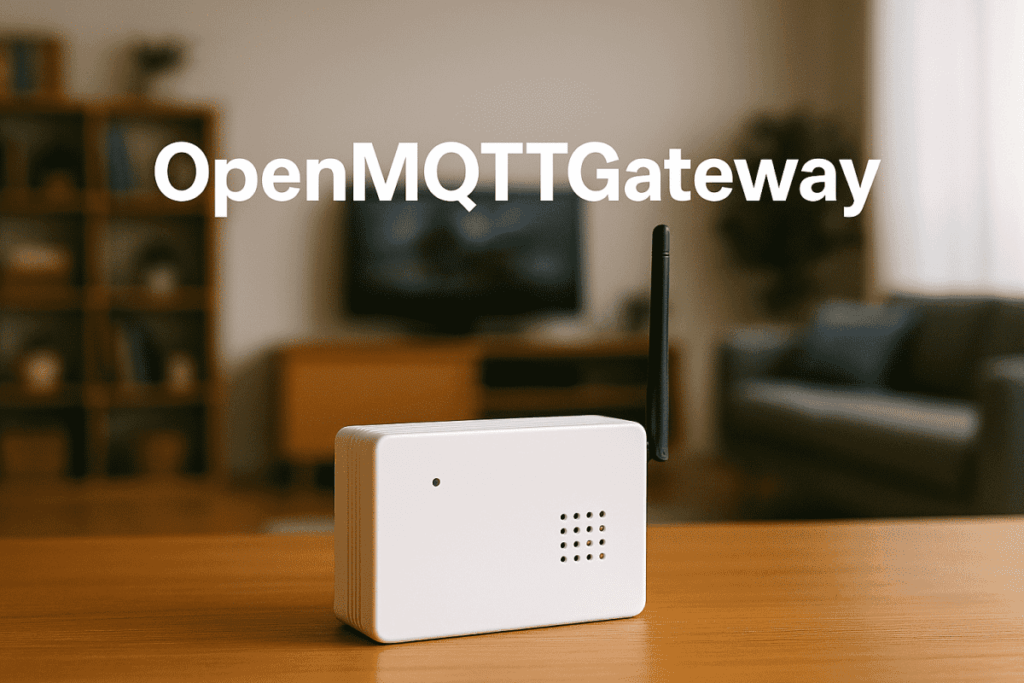
OpenMQTTGateway: Unifying Multi-Protocol IoT Devices with an ESP32-Based MQTT Framework
OpenMQTTGateway is an open-source ESP32 MQTT gateway bridging BLE, RF, and IR for scalable IoT integration. Explore enterprise IoT solutions.

What is Retail IoT? How Smart Technology Transforms Store Operations
See how Retail IoT powers smarter stores—cut costs, boost customer experience, and streamline Store Operations Management.
Smart Retail Signage Management: Unified Campaigns Across Multi-Store Chains
In-store digital signage management made simple. Centralize campaigns across stores with smart retail SaaS — faster rollouts, lower costs, measurable ROI.
AI Voice Ads in Retail Store: From Static Screens to Interactive Digital Signage
AI voice ads in retail stores turn screens into smart assets, boosting ROI with real-time interactions, centralized control, and measurable results.
Smart Store Refrigeration Management: Real-Time Monitoring and Energy Optimization
Smart store refrigeration management helps retailers cut cooling energy by up to 15% and lower spoilage with real-time monitoring and smart thermostats.
Need to apply one of these ideas to your device or platform?
Share your device type, protocol, site conditions, platform goals, or AI workflow. We can help you evaluate the most practical implementation path.