A Node RED Modbus server is one of the simplest ways to connect industrial Modbus TCP devices to modern IoT platforms. In this guide, we show how to build a Node-RED Modbus Server and forward device telemetry to MQTT.
This solution supports traditional Modbus devices while integrating with modern cloud platforms.
Why Node-RED + Modbus Server + MQTT?

In industrial IoT (IIoT), Modbus TCP is still one of the most widely used protocols. Many PLCs, meters, and sensors rely on it for status reporting or parameter reading. A common setup in industrial projects is using a node red modbus tcp flow to read holding registers and process device telemetry before sending it to MQTT.
Most traditional industrial software is difficult to scale or integrate with MQTT or cloud IoT platforms or custom systems like ZedIoT.
Node-RED fills that gap because it:
- Supports Modbus, MQTT, HTTP and other common protocols
- Uses a visual flow editor with very little coding
- Has a large plugin ecosystem
- Runs on Linux servers, Docker, and edge devices
For this reason, “Node-RED + Modbus Server + MQTT” is a flexible and portable solution for industrial data acquisition.
What is node-red-contrib-modbus ? (Required Plugin)
To use Modbus inside Node-RED, you need the community package:
node-red-contrib-modbusInstall it from:
Menu → Manage palette → Install → search “node-red-contrib-modbus”
This package provides all essential nodes:
- Modbus Server (to simulate or host a Modbus slave)
- Modbus Read / Write
- Modbus Flex Getter
- Modbus Client
This aligns your content with users searching for:
“node red modbus server/node red modbus client / modbus write / modbus tcp server”.
Architecture Overview
Most industrial devices operate as Modbus TCP Clients (masters).
Node-RED acts as a Modbus Server (slave) and exposes register space.
Node-RED then uses its Modbus Client nodes to poll its own Server, read updated register values, and push structured data to an MQTT Broker such as EMQX, Mosquitto, or ZedIoT MQTT.
Flow summary:
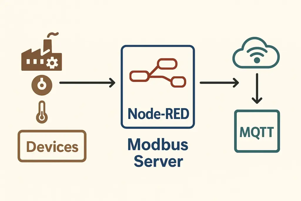
Device → Node-RED Modbus Server → Node-RED Modbus Read → Parse → MQTT → CloudBelow is the architecture diagram (unchanged from your original):
This architecture effectively works as a lightweight modbus mqtt gateway, bridging traditional Modbus TCP devices with cloud-based IoT platforms.
---
title: "Node-RED Modbus Server → MQTT Multi-Layer Data Flow Architecture"
---
graph TD

%% ===== Style Definitions =====
classDef field   fill:#FFEED6,stroke:#E67E22,stroke-width:2,rx:10,ry:10,color:#6E2C00,font-weight:bold;
classDef nodered fill:#E3F2FD,stroke:#1976D2,stroke-width:2,rx:10,ry:10,color:#0D47A1,font-weight:bold;
classDef logic   fill:#F3E5F5,stroke:#8E24AA,stroke-width:2,rx:10,ry:10,color:#4A148C,font-weight:bold;
classDef mqtt    fill:#E2F7E2,stroke:#2E7D32,stroke-width:2,rx:10,ry:10,color:#1B5E20,font-weight:bold;
classDef cloud   fill:#FFF4C2,stroke:#F4A300,stroke-width:2,rx:10,ry:10,color:#5D4037,font-weight:bold;
classDef note    fill:#FFF9E6,stroke:#E6A700,stroke-width:1.5,rx:8,ry:8,color:#5D3B00;

linkStyle default stroke:#555,stroke-width:1.5;

%% ===== Layer 1: Field Devices (Modbus TCP Clients) =====
subgraph L1["① Field Device Layer (Modbus TCP Clients)"]
direction LR
A1["🏭 PLC / Control CabinetModbus TCP Client #1"]:::field
A2["⚙️ VFD / Motor DriverModbus TCP Client #2"]:::field
A3["🌡️ Temperature / Pressure Sensor GatewayModbus TCP Client #3"]:::field
end

%% ===== Layer 2: Node-RED Modbus Access Layer =====
subgraph L2["② Node-RED Modbus Access Layer"]
direction TB
B1["🖧 Modbus Server (TCP 1502)Unified Register Entry"]:::nodered
B2["📘 Modbus Read ClientPeriodic Register Polling"]:::nodered
B3["✏️ Modbus Write ClientWrite Control Commands (Optional)"]:::nodered
end

%% ===== Layer 3: Node-RED Logic & Processing Layer =====
subgraph L3["③ Node-RED Rule Engine & Data Processing"]
direction LR
D1["⚙️ Function: Parse RegistersUnit Conversion / Field Mapping"]:::logic
D2["🚨 Function: Alert RulesThreshold Check / State Machine"]:::logic
D3["📊 Node-RED DashboardLocal Monitoring UI"]:::logic
end

%% ===== Layer 4: MQTT & Cloud Platforms =====
subgraph L4["④ MQTT & Cloud Platform Layer"]
direction LR
E1["☁️ MQTT BrokerZedIoT / Mosquitto"]:::mqtt
E2["📈 ZedAIoT Cloud PlatformTime-Series Storage / AI Analysis"]:::cloud
E3["🔧 Other Subscriberse.g., InfluxDB / Other Node-RED Flows"]:::mqtt
end

%% ===== Field Devices → Node-RED Modbus Flow =====
A1 -->|"Read/Write Registers"| B1
A2 -->|"Read/Write Registers"| B1
A3 -->|"Read/Write Registers"| B1

B1 -->|"Register Buffer / Holding Registers"| B2
B1 -->|"Control Command Write (Optional)"| B3

%% ===== Node-RED Internal Processing Flow =====
B2 -->|"Raw Register Values"| D1
D1 -->|"Structured Data (JSON)"| D2
D1 -->|"Real-time Data"| D3
D2 -->|"Telemetry / Alert Messages"| E1

%% ===== MQTT / Cloud Distribution =====
E1 -->|"Topic: factory/+/telemetry"| E2
E1 -->|"Topic: factory/+/alert"| E3
A node red modbus server makes it easy to simulate a Modbus slave and centralize register updates before converting them to JSON.
How the Node-RED Modbus Server Works

When the node red modbus server receives register writes, the Modbus Read node can poll and extract the latest values for processing.
1. How do devices send data to Node-RED?
Modbus devices don’t “push” data. They write into server registers using:
- FC06 — Write Single Register
- FC16 — Write Multiple Registers
Node-RED’s modbus-server saves these values in its internal register buffer.
2. Why does Node-RED still need Modbus Read?
Important:modbus-server does NOT output messages.
To read values, you must poll it using:
modbus-read- or
modbus-flex-getter
This is the core design pattern of a Node-RED Modbus gateway.
3. Converting Modbus registers to MQTT
msg.topic = "iot/device001/telemetry";
msg.payload = {
    temperature: msg.payload[0] / 10,
    humidity: msg.payload[1] / 10,
    ts: Date.now()
};
return msg;
This JSON is then published through MQTT.
Deploying Node-RED with Docker
Using Docker gives better stability, easier upgrades, and consistent environments.
Minimal deployment:
docker run -d \
  --name nodered-modbus \
  -p 1880:1880 \
  -p 1502:1502 \
  -v /opt/nodered_data:/data \
  -e TZ=Asia/Shanghai \
  nodered/node-red:latest
Parameters
| Port/Setting | Description |
|---|---|
| 1880 | Node-RED Editor UI |
| 1502 | Modbus Server port |
| /opt/nodered_data | Persistent flows and plugins |
| TZ | Timezone for logs |
Access the UI:
http://SERVER_IP:1880Installing Modbus & MQTT Nodes
In Node-RED:
Navigate to:
Menu → Manage palette → Install
Install:
node-red-contrib-modbusnode-red-node-mqtt(if not present)
You will then see:
- Modbus nodes: server/read/write/flex-getter
- MQTT nodes: mqtt in/out
Setting Up a Modbus TCP Server in Node-RED
Add a modbus-server node and configure:
- Name: Modbus TCP Server (1502)
- Host: 0.0.0.0
- Port: 1502
- Unit ID: 1
- Holding Registers: 1024
- Input Registers: 1024
This server now acts as a Modbus slave that PLCs and instruments can write to.
Polling the Server (Critical Step)
Because the server does not emit data, you must poll it.
Example Modbus Read config:
- Unit ID: 1
- Function: FC3 — Read Holding Registers
- Address: 0
- Quantity: 4
- Poll Rate: 1 sec
- Server: 127.0.0.1:1502
Flow:
(modbus-read) → (function decode) → (mqtt out)
                         ↘ (debug)
Parsing Register Data
Example function used to decode Modbus registers:
let r = msg.payload;

msg.payload = {
  temperature: r[0] / 10,
  humidity: r[1] / 10,
  status: r[2],
  ts: Date.now()
};

msg.topic = "iot/modbus/device001/telemetry";
return msg;
This is where you can add unit conversions, filtering, or rule logic.
This parsing function is typical for a node red modbus server that needs to convert raw register values into MQTT-friendly payloads.
MQTT Output
Configure MQTT Out:
- Broker: mqtt.example.com
- Port: 1883 or 8883
- Auth: Based on your MQTT server
- Client ID: modbus-gateway-01
If the Topic field is empty, the message uses msg.topic.
Testing Your Node-RED Modbus Server
Method 1 — Using Modbus Client Tools
Recommended tools:
| Tool | OS | Notes |
|---|---|---|
| QModMaster | Win/Mac/Linux | Free, simple UI |
| Modbus Doctor | macOS | Available in App Store |
| Modbus Poll | Windows | Industry standard |
Test parameters:
- Host: server IP
- Port: 1502
- Unit ID: 1
- Function: FC06
- Address: 0
- Value: 1234(e.g., 123.4°C)
If successful, your modbus-read node will display:
[1234, 0, 0, 0]Method 2 — Loopback Test in Node-RED
Flow:
(inject) → (modbus-write)
(modbus-read) → (debug)
This validates your gateway without external devices.
Complete Importable Node-RED Flow (JSON)
Here is a ready-to-import Node-RED flow for a Modbus Server + Modbus Read + MQTT gateway.
It includes the minimal architecture and parsing logic, and can be used directly or customized for your own device protocol.
You can copy the JSON below and import it into Node-RED:
Menu → Import → Clipboard → Paste → Deplo
[
  {
    "id": "modbus-flow",
    "type": "tab",
    "label": "Modbus Gateway",
    "disabled": false
  },
  {
    "id": "modbus-server-1502",
    "type": "modbus-server",
    "z": "modbus-flow",
    "name": "Modbus Server 1502",
    "logEnabled": true,
    "serverPort": 1502,
    "hostname": "0.0.0.0",
    "responseDelay": 100,
    "delayUnit": "ms",
    "coilsBufferSize": 1024,
    "holdingBufferSize": 1024,
    "inputBufferSize": 1024,
    "discreteBufferSize": 1024,
    "unitid": 1,
    "x": 200,
    "y": 80,
    "wires": [[],[],[]]
  },
  {
    "id": "modbus-client-127",
    "type": "modbus-client",
    "name": "Local Client 1502",
    "tcpHost": "127.0.0.1",
    "tcpPort": "1502",
    "unit_id": 1,
    "clienttype": "tcp",
    "bufferCommands": true,
    "parallelUnitIdsAllowed": true
  },
  {
    "id": "modbus-read-hr",
    "type": "modbus-read",
    "z": "modbus-flow",
    "name": "Read HR(0..3)",
    "dataType": "HoldingRegister",
    "adr": "0",
    "quantity": "4",
    "rate": "1",
    "rateUnit": "s",
    "server": "modbus-client-127",
    "x": 210,
    "y": 160,
    "wires": [["fn-decode"],[]]
  },
  {
    "id": "fn-decode",
    "type": "function",
    "z": "modbus-flow",
    "name": "Decode Registers and Send to MQTT",
    "func": "let reg = msg.payload;\n\nlet data = {\n    temperature: reg[0] / 10,\n    humidity: reg[1] / 10,\n    status: reg[2],\n    ts: Date.now()\n};\n\nmsg.topic = \"iot/modbus/device001/telemetry\";\nmsg.payload = data;\nreturn msg;",
    "outputs": 1,
    "x": 430,
    "y": 160,
    "wires": [["mqtt-out","debug-decoded"]]
  },
  {
    "id": "mqtt-out",
    "type": "mqtt out",
    "z": "modbus-flow",
    "name": "MQTT Server",
    "broker": "mqtt-broker",
    "topic": "",
    "qos": "",
    "retain": "",
    "x": 680,
    "y": 160,
    "wires": []
  },
  {
    "id": "debug-decoded",
    "type": "debug",
    "z": "modbus-flow",
    "name": "Decoded Data",
    "complete": "payload",
    "x": 690,
    "y": 220,
    "wires": []
  },
  {
    "id": "mqtt-broker",
    "type": "mqtt-broker",
    "name": "MQTT Example",
    "broker": "YOUR_MQTT_HOST",
    "port": "1883",
    "clientid": "modbus-gateway-01",
    "usetls": false
  }
]---
You only need to modify the following values:
- YOUR_MQTT_HOST → your actual MQTT broker address
- iot/modbus/device001/telemetry → your custom MQTT topic
- Parsing logic → adjust according to your device protocol
After these changes, the flow can be used immediately.
Troubleshooting
1. Modbus client cannot connect to the Server
Check whether the Docker port mapping is correct:
docker ps
# You should see: 0.0.0.0:1502->1502/tcp
Ensure the port is not already in use::
sudo lsof -i:15022. No data appears in the Node-RED Debug panel
Most common cause:
You connected a debug node directly after
modbus-server, but this node does not output any messages.
Solution (critical):
✔ Use modbus-read or modbus-flex-getter
✔ Poll the Modbus Server from within Node-RED
✔ Connect your debug node after the output of these nodes
3. MQTT messages not being published
Check:
- Is the broker address correct?
- Are you using the correct port (1883 vs 8883 for TLS)?
- Is the topic correct?
- Is port 1883 allowed in your firewall settings?
Advanced Usage: Multi-Device, Multi-Register, Multi-Topic Support
In real industrial deployments, a single gateway often handles multiple Modbus devices, multiple Unit IDs, and multiple register areas. You can scale this architecture as follows:
- Add multiple modbus-read nodes, each polling a different
unitId - Use a function node to generate dynamic topics, for example:
msg.topic = `iot/modbus/${unitId}/telemetry`;
- Use a switch node to route traffic based on register addresses
- Add local buffers, accumulators, or filters to build advanced rule engines
You can also integrate:
- InfluxDB for time-series storage
- Grafana dashboards
- ZedIoT Rule Engine
- Alerts via Webhook / Email / DingTalk / Slack
Together, these form a complete industrial IoT edge computing gateway.

By using a node red modbus server as the gateway layer, you can unify industrial Modbus TCP devices and push telemetry reliably to MQTT.
This solution is lightweight, flexible, and cross-platform—ideal for both small setups and enterprise-level industrial IoT deployments.
Need a custom Modbus-to-MQTT gateway?
We build industrial data acquisition gateways using Node-RED, Modbus TCP/RTU, MQTT, and cloud platforms.
Contact us for a free technical assessment.
FAQ
1. What is a node red modbus server?
A node red modbus server is a Modbus TCP slave implemented inside Node-RED. It exposes registers so Modbus devices can read and write data through TCP. This lets Node-RED act as a lightweight industrial gateway.
2. How do I read and write Modbus registers in Node-RED?
You use the modbus-read node to poll holding registers and the modbus-write node to send control commands. This forms a simple node red modbus read write workflow for industrial devices.


