

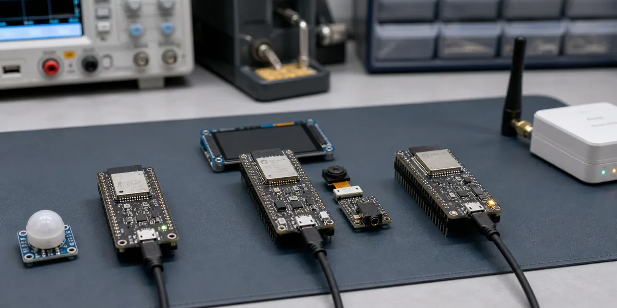
For a connected sensor or compact controller, ESP32-C3 is usually the lowest-risk starting point. If the device must combine a display, camera, audio, USB, or local inference, validate ESP32-S3 first. If the roadmap explicitly requires on-chip 802.15.4, particularly Matter over Thread or Zigbee, validate ESP32-C6 first. This is not a ranking by age or headline clock speed. Each chip defines a different system boundary.
The decision should be made against peak memory, concurrent peripherals, radio requirements, OTA rollback, and the maintenance path after security features are enabled. A successful prototype only proves that the happy path ran once. A production selection needs measurable margin under the worst workload.
The short answer
| Product constraint | First candidate | Why | What still needs proof |
|---|---|---|---|
| Wi-Fi + BLE sensing, control, or a cost-sensitive node | ESP32-C3 | Focused single-core RISC-V platform with Wi-Fi 4 and BLE 5 | Peak heap, TLS/OTA concurrency, GPIO and factory debug |
| Display, camera, audio, USB OTG, or heavier local processing | ESP32-S3 | Dual-core, vector instructions, LCD/camera and USB OTG fit the workload | PSRAM variant, bandwidth contention, model arena and thermal/power margin |
| Thread/Zigbee, Matter over Thread, or a Wi-Fi 6 roadmap | ESP32-C6 | Integrates Wi-Fi 6, BLE, and IEEE 802.15.4 | Multiprotocol coexistence, antenna, certification, stack and OTA headroom |
Two distinctions prevent expensive mistakes. C3 and C6 include USB Serial/JTAG, but that is not the general USB OTG capability offered by S3. Also, Matter does not automatically require C6: Matter can run over Wi-Fi. C6 becomes the clear route when Thread or another on-chip 802.15.4 use case is part of the product contract.
Freeze the workload before comparing chips
Turn the product brief into a measurable workload sheet:
- Connectivity: simultaneous Wi-Fi/BLE, TLS sessions, MQTT reconnects, local discovery, or Thread/Zigbee.
- Data path: sensor rate, audio frames, image size, ring buffers, offline queue, and retained logs.
- Interaction: display refresh, touch, USB, camera, wake word, and the maximum user-visible response time.
- Maintenance: A/B OTA, rollback, crash capture, field diagnostics, Secure Boot, Flash Encryption, and key rotation.
“MQTT works” is not a memory test. Peak pressure may occur when TLS reconnect, OTA download, log writes, and sensor acquisition overlap. A system can report adequate total free heap yet still fail a large contiguous allocation. Test the combined condition instead of estimating each subsystem in isolation.

Convert specifications into firmware consequences
Espressif documents ESP32-C3 as a single-core RISC-V device up to 160 MHz with 400 KB of on-chip SRAM, 2.4 GHz Wi-Fi 4, and Bluetooth 5 LE. ESP32-S3 has two Xtensa LX7 cores up to 240 MHz, 512 KB of on-chip SRAM, vector instructions, LCD/camera support, and USB OTG. ESP32-C6 differentiates itself with Wi-Fi 6, BLE, IEEE 802.15.4, and high-performance plus low-power RISC-V cores. Package, flash, PSRAM, and pin availability still depend on the selected SoC revision and module.
Those specifications change architecture decisions:
- C3's single core is sufficient for many nodes, but the network stack, application tasks, and interrupt service compete more directly. Task priorities, non-blocking drivers, and reconnect-time latency must be deliberate.
- S3's second core and vector support create room for richer edge workloads, but do not remove memory and bandwidth limits. A framebuffer, camera DMA, audio buffers, and PSRAM traffic can contend at the same time.
- C6 is primarily a protocol-roadmap decision, not a replacement for S3 multimedia. Thread/Zigbee and Wi-Fi/BLE coexistence bring RF scheduling, certification, and stack-resource work.
Use the official ESP32-C3 datasheet, ESP32-S3 datasheet, and ESP32-C6 datasheet as the baseline. Record the chip revision, ESP-IDF version, module, and differences between the development kit and production PCB with the decision.
Build a firmware budget, not a flash-size guess
Create a resource budget before schematic freeze and make CI report the same measures on every build.
| Budget | Design record | Validation | Failure signal |
|---|---|---|---|
| Flash/partitions | bootloader, NVS, dual OTA slots, filesystem, recovery | inspect partition table and artefacts | new image no longer fits the smaller OTA slot |
| Internal SRAM | static data, stacks, DMA memory, peak heap | heap tracing under combined workloads | TLS/OTA overlap causes allocation failure |
| External PSRAM | framebuffer, model, caches and access pattern | degraded test with PSRAM constrained | a real-time path depends on uncontrolled latency |
| CPU/real time | worst task utilisation, interrupt and watchdog margin | p95/p99 latency under stress | a reconnect delays the control loop |
| Flash endurance | NVS, logs, queue and update frequency | write amplification and power-cut tests | every state change creates a synchronous write |
PSRAM is not unlimited memory. It depends on the S3 module/variant and is commonly useful for large buffers, framebuffers, or model data. It should not blindly absorb every real-time allocation. Espressif's LCD documentation notes that framebuffers, CPU activity, and EDMA can share PSRAM bandwidth and become starved. Measure display, network, and local processing concurrently.
Tie that budget to a repeatable peak-load scenario. A display device may look comfortable on a static page, then encounter DNS and TLS reconnect, OTA metadata download, screen refresh, sensor acquisition, and offline-queue writes at once. Record minimum free heap, largest free block, task-stack high-water marks, watchdog events, dropped frames, and business-response latency for a fixed workload. Replay it after ESP-IDF, TLS, model, or partition changes. If C3 retains stable margin, moving to S3 does not automatically improve the product; if the failure is a non-separable memory peak or scheduling conflict, isolated micro-optimisations may only defer the architecture decision.
Freeze a chip together with its module, partition table, ESP-IDF baseline, and security configuration. Modules based on the same SoC can differ in flash, PSRAM, antenna arrangement, and usable pins, while a development board may hide power or programming constraints with external components. The design record should therefore name the module, substitution rules, strapping pins, antenna clearance, peak supply assumptions, and download/JTAG path. This makes a module substitution or SDK upgrade trigger the right validation instead of being treated as an equivalent “same ESP32” change.
TinyML: S3 is a natural candidate, not an automatic pass
For wake words, vibration classification, small vision features, or compact detection models, S3's dual cores, vector instructions, and optional PSRAM often make it the practical first candidate. ESP-DL also treats quantisation as central on memory-constrained devices. But loading a model is not the acceptance criterion. Freeze and measure:
- input shape, supported operators, INT8/INT16 method, and representative calibration data;
- peak tensor arena, weights, preprocessing, and business buffers at the same time;
- end-to-end latency including acquisition, preprocessing, inference, postprocessing, and transmission;
- p95/p99 latency and watchdog behaviour while Wi-Fi, display, or audio is active;
- accuracy, false positives, false negatives, and an explicit uncertain/manual-review path.
C3 can execute sufficiently small models, so it should not be excluded by name. Conversely, an unsupported operator set, large image pipeline, or Linux-class runtime can exceed S3's sensible boundary. The right answer may be an MCU plus a dedicated accelerator or application processor. See our ESP32-S3 TinyML optimisation guide for the memory and quantisation path.
Matter and Thread: identify the network bearer first
“Support Matter” is not yet a complete requirement. Is it Matter over Wi-Fi or Matter over Thread? Does the product also need Zigbee? Is the device an end device, router, bridge, or part of a border-router system? How do commissioning, local control, and cloud control degrade independently?
For on-chip Thread or Zigbee, C6's IEEE 802.15.4 radio is a direct advantage. For Matter over Wi-Fi, C3, S3, and C6 can all be candidates depending on memory, peripherals, and the certification plan. Protocol availability does not equal a certifiable product: antenna design, RF coexistence, credentials, device attestation, commissioning UX, and stack-version control remain production work.
A gateway or bridge can also accumulate too many roles. Combining 802.15.4, Wi-Fi backhaul, model translation, OTA, and local rules on one MCU expands the fault domain. A radio coprocessor separated from the primary controller can sometimes produce a cleaner upgrade and certification boundary.
Prove the selection with a failure matrix
Before freezing the chip, run combinations that represent field failure rather than a feature demo.
| Scenario | Injection | Observe | Acceptance direction |
|---|---|---|---|
| Network recovery | AP loss, weak RF, DNS/TLS failure | reconnect time, heap, task starvation | no reboot, critical state retained, bounded backoff |
| OTA/rollback | interrupted download, corrupt image, failed first boot | boot slot, rollback reason, recovery time | automatic return to a known-good version |
| Peripheral concurrency | display/audio/camera/sampling together | p99 latency, DMA errors, dropped frames | core control and acquisition stay within limits |
| Power faults | slow ramp, brownout, repeated restart | NVS, filesystem, boot count | no unrecoverable corruption |
| Security lifecycle | Secure Boot, Flash Encryption, eFuse, debug policy | provisioning, service, key workflow | controlled production and RMA path |
| Batch/environment | multiple boards, temperature and supply corners | RF, boot, power and sensor drift | traceable results across units |
Do not postpone the security lifecycle. Secure Boot, Flash Encryption, and eFuse decisions can change JTAG, download, and repair access. Rehearse key injection, recovery, and RMA on a pre-production batch.
The failure matrix must also separate a silicon limit from an integration defect. A control timeout during weak-signal reconnect could indicate CPU contention, but it could also come from a driver holding a lock, synchronous logging, or an incorrect backoff policy. Replacing C3 with S3 may hide the symptom without fixing the failure mode. Associate each result with reset reason, heap low-water mark, stack high-water mark, state-machine timing, and OTA rollback reason; upgrade the chip only after the evidence shows that the required workload still crosses the resource or peripheral boundary.
When none of these chips is the right boundary
High-resolution multi-stream video, complex Linux applications, containers, browser-class UI, large-model inference, or substantial local storage may already be outside a sensible MCU boundary. Consider a Linux SoC, an MCU/MPU split, or a dedicated accelerator. Preserving a one-chip BOM by sacrificing observability, rollback, and performance margin usually moves cost into field maintenance.
Do not upgrade an established C3 product merely because S3 or C6 exposes more features. A mature C3 design may already have a stable BSP, fixture, certification, and supply chain. Migration reopens drivers, RF, power, factory testing, and OTA risk. It is justified when a measured new workload crosses the current boundary.
Recommendation
- Choose
ESP32-C3when the product is a focused Wi-Fi/BLE sensing or control node and worst-case heap, latency, and OTA have passed. - Choose
ESP32-S3when USB OTG, display, camera, audio, or TinyML is the core workload and PSRAM/bandwidth/real-time margin is demonstrated. - Choose
ESP32-C6when Thread, Zigbee, or a Wi-Fi 6 roadmap is explicit and coexistence, certification, and OTA resource costs are in the plan.
If the requirements still cannot be converted into a module, partition table, driver boundary, and validation matrix, another comparison table will not close the gap. Our ESP32 development services and embedded development services cover requirements, board constraints, ESP-IDF firmware, OTA, security, and production test—while identifying workloads that should not remain on one MCU.
This guide uses public Espressif documentation and does not include a controlled, cross-chip benchmark on identical boards, firmware, and lab conditions. It therefore makes no universal promise about power, BOM, RF, TinyML latency, or certification. Re-test all numbers on the selected module, PCB, ESP-IDF release, and production configuration.