

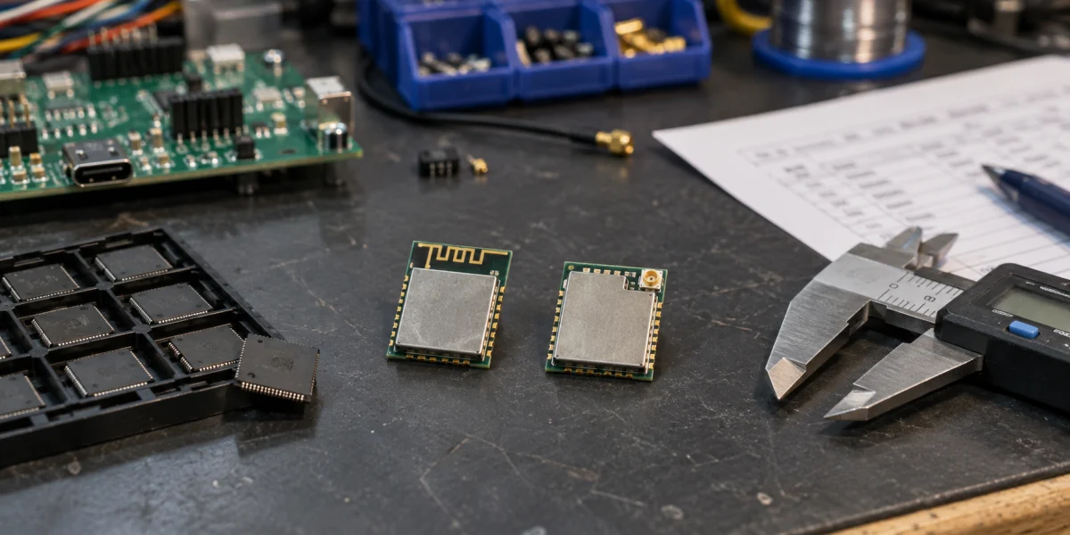
“Use an ESP32-S3” selects a chip family, not a complete purchasing item. The SoC supplies processing, wireless, and peripheral capabilities. A module integrates the SoC with supporting circuitry. Its full part number identifies the particular module variant, including the relevant antenna and memory configuration.
Start with modules if the team is not prepared to own chip-level support circuitry and RF design. Then narrow the choice to a part number listed in the manufacturer's documentation, and attach the project's validation conditions and substitution limits to the request for quotation. A module changes the integration workload; it does not remove responsibility for validating the finished product.
Two N16 parts, two different integration choices
The ESP32-S3-WROOM-1 / WROOM-1U datasheet v1.8, Section 1.2, lists both of the following parts. These are published specifications, not evidence of stock or a supplier quotation.
| Item | ESP32-S3-WROOM-1-N16 | ESP32-S3-WROOM-1U-N16 |
|---|---|---|
| SoC family | ESP32-S3 | ESP32-S3 |
| Flash / PSRAM | 16 MB / none | 16 MB / none |
| Antenna | On-board PCB antenna | External antenna connector |
| Recommended ambient range | −40 to 85 °C | −40 to 85 °C |
| Dimensions in the series table | 18.0 × 25.5 × 3.1 mm | 18.0 × 19.2 × 3.2 mm |
Matching processing and storage specifications do not settle the mechanical design. WROOM-1 needs an appropriate location for its PCB antenna within the board and enclosure arrangement. WROOM-1U requires the external antenna and its connection to become part of that arrangement. A shorter module body does not necessarily produce a smaller complete assembly once the cable and antenna are included.
Different dimensions should not be mistaken for proof of different pin assignments. Section 3.1 explicitly applies the same pin diagram to both modules, while noting that the 1U lacks the illustrated PCB-antenna keepout zone. That shared diagram is still insufficient to authorize a substitution. Check each module's dimensions and recommended land pattern in Sections 10 and 11 against the actual board and enclosure.
This is the work left after choosing the chip family. Firmware approval of ESP32-S3 answers part of the functional question. Hardware and mechanical design must still establish how it fits into the product before purchasing can treat either module as an approved material.
Keep the SoC, module, and development board decisions separate
Espressif's guide to module part numbers distinguishes a chip-level SoC from a module that includes supporting components such as a crystal and RF matching network. Memory and antenna arrangements depend on the product variant. Choosing a module is therefore a decision about integrated hardware conditions, not simply a way to select a more capable processor.
A development board adds another layer, typically combining a chip or module with power, debugging connections, buttons, and headers. It is useful for checking software behavior, but its board name should not replace the surface-mount module's part number in a purchasing record. Record the actual module and memory configuration when evaluating software, too: a demonstration running on a PSRAM-equipped board does not establish that a candidate without PSRAM will be adequate.
These distinctions help route a failed requirement to the right decision. Missing wireless or peripheral capabilities send the team back to chip selection. An unsuitable antenna, package, or memory combination calls for another module candidate. Convenient programming and test connections are development-board concerns. Solving one layer does not silently resolve the others.

The full part number identifies a candidate that can be checked. Quotation, validation, and approval remain separate steps.
Eliminate candidates using product constraints
Decide where the antenna will operate
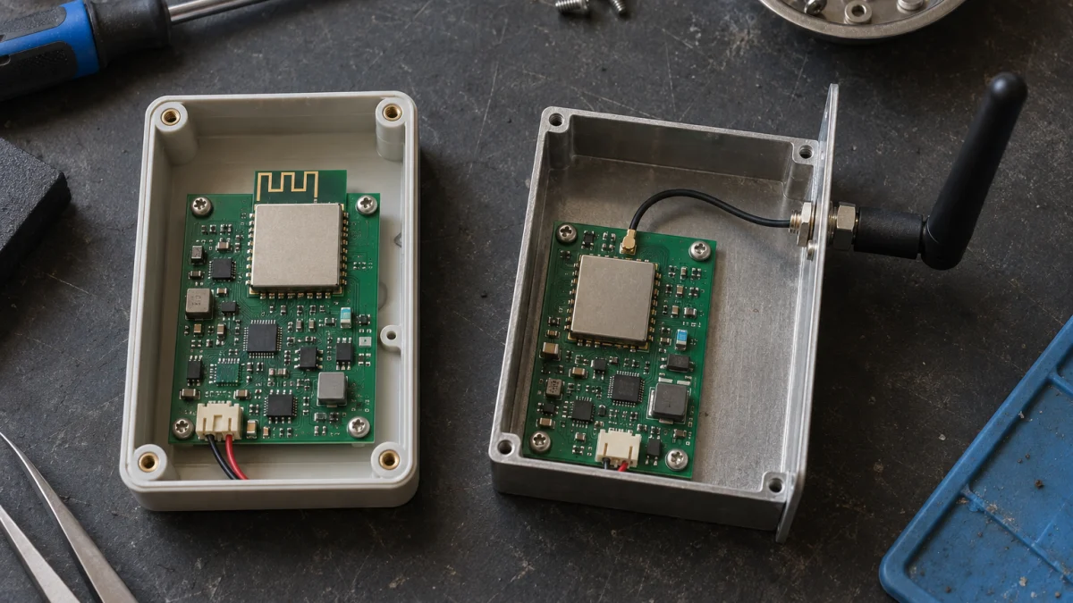
Illustrative scene: the left design uses a PCB antenna; the right uses a cable to an antenna outside the enclosure. These layouts are not reference designs or evidence of compliant clearance or RF performance.
The antenna is not an accessory to select after the module decision. If the main board sits deep inside a metal enclosure, establish where the radiating element can be placed. An external connection may make a usable position possible, but it also introduces antenna selection, cable routing, mechanical retention, and assembly checks. Keeping a PCB-antenna candidate solely to avoid a cable is not a sound decision if the required placement cannot be accommodated.
A plastic-enclosure design that meets the layout requirements may avoid those additional external components by using a PCB antenna. That is not a promise of better reception. Espressif's ESP32-S3 PCB layout guidance calls for considering the base board and housing, and testing throughput and communication range in the final product. A selection review should include the antenna's proposed physical location, not merely its type.
Keep antenna suitability open until the relevant prototype checks are complete. A later enclosure revision that moves a battery, metal support, or cable harness near the antenna can change the validation conditions without changing the module part number. The project then needs to decide whether its previous evidence still covers the new arrangement.
Read memory and temperature as a combination
Flash capacity and runtime memory solve different problems. Firmware images, update partitions, and persistent data consume storage; allocations and image or audio buffers create runtime memory demand. Ask the software team for separate budgets and measurements, then look for an actual listed combination. “16 MB memory” is too ambiguous to serve both purposes.
The v1.8 table illustrates why the temperature column cannot be selected independently. N16R8 adds 8 MB PSRAM but has a listed ambient ceiling of 65 °C. H4 instead provides 4 MB Flash and a 105 °C ceiling, with a footnote directing customers to contact Espressif for customization. Neither is an automatic upgrade or substitute for N16 merely because one specification is higher. See the series comparison and notes in Section 1.2.
That section also describes a conditional option for R8/R16V variants: enabling Octal SPI PSRAM ECC raises the stated ceiling to 85 °C while reducing usable PSRAM by 1/16. If a selection depends on that condition, record the required software configuration, available capacity, and outstanding verification. Do not turn a conditional specification into an unconditional RFQ requirement.
The datasheet defines ambient temperature at the environment immediately outside the module. It is not automatically the air temperature outside the finished product. Suitability inside a closed enclosure needs to be assessed against conditions at the module's location. Without those measurements, a part can remain a candidate, but the product's operating range is not a verified result. Calling the requirement “industrial grade” does not resolve it.
A chip-level design needs a stronger case than a lower unit price
Direct SoC integration deserves evaluation when available modules cannot meet a specific size, peripheral, or other hard constraint. It is not simply a module with its cover removed. Espressif's PCB layout guidance addresses chip power, crystal, RF, and memory routing separately. On a custom chip-level board, the project owns the implementation of work otherwise integrated into the module.
Begin that evaluation with the unmet requirement, then identify responsibility for schematic design, RF tuning, prototype validation, and retesting after changes. Without the people and a validation plan, moving to a SoC transfers an unresolved problem onto the team's own board. Conversely, a module's convenience is not a reason to ignore a genuine mechanical or interface conflict that makes it unsuitable.
Only then is a cost comparison useful. A chip quotation below a module quotation does not establish a lower total product cost. Supporting components, PCB fabrication, assembly, development, and testing belong in the same comparison. This article has no project quotations, volume assumptions, or validation records from which to calculate a break-even production quantity.
Specify what a supplier may not silently replace
It is reasonable to request a quotation before completing end-product validation, provided a candidate is not presented as production-approved. Suppose a project requires an external antenna, 16 MB Flash, and no PSRAM for the current software scope. ESP32-S3-WROOM-1U-N16 can enter a candidate RFQ. The example matches published characteristics to those stated requirements; it is not a completed design freeze for a real product.
Make the RFQ traceable with more than a long component name:
- Ordering identity: full manufacturer part number, datasheet revision, and verification date.
- Required characteristics: Flash, PSRAM, antenna type, ambient range, and any software configuration on which the choice depends.
- Design references: board and enclosure revisions, land-pattern review, and external antenna and connection arrangement where applicable.
- Open items: certificate applicability for the target market, prototype validation, quotation, lead time, and actual supply confirmation.
- Substitution rule: no unapproved replacement; a proposed alternative must include its full part number and differences for project review.
The certification item should not simply say “certified.” Espressif's certifications and compliance index helps locate regional entries for specific modules. The compliance owner still needs to check the intended market, applicable configuration, and finished-product obligations. Finding a module in the index does not establish that the current product is approved for sale.
These records bind the candidate to its conditions of use. If the selection relies on ECC, disabling it requires reassessing temperature and capacity. A board or enclosure revision similarly requires checking whether antenna validation remains applicable. When a supplier proposes a different memory or antenna variant, a shared family name must not override that review. Keep the quotation, prototype results, and approval record separate so that commercial confirmation does not stand in for technical acceptance.
The practical endpoint is agreement between chip capability, integration responsibility, and a specific variant. A module that fits the antenna, memory, temperature, and mechanical requirements can proceed to quotation and validation. When available modules fail a hard requirement and the team can own design and verification, evaluate direct SoC integration. Freeze the material only after confirming the project conditions and substitution boundaries.
This is a public-document-based selection method. It does not review a real BOM, quotation, prototype, thermal measurement, RF test, or end-product certification record, and does not establish cost, lead time, production reliability, or substitution feasibility for the examples.
Further reading
- Still deciding on the chip family? See ESP32-C3 vs S3 vs C6: firmware and production tradeoffs.
- Already have a module name to check? See how to read Espressif ESP32 module part numbers.