

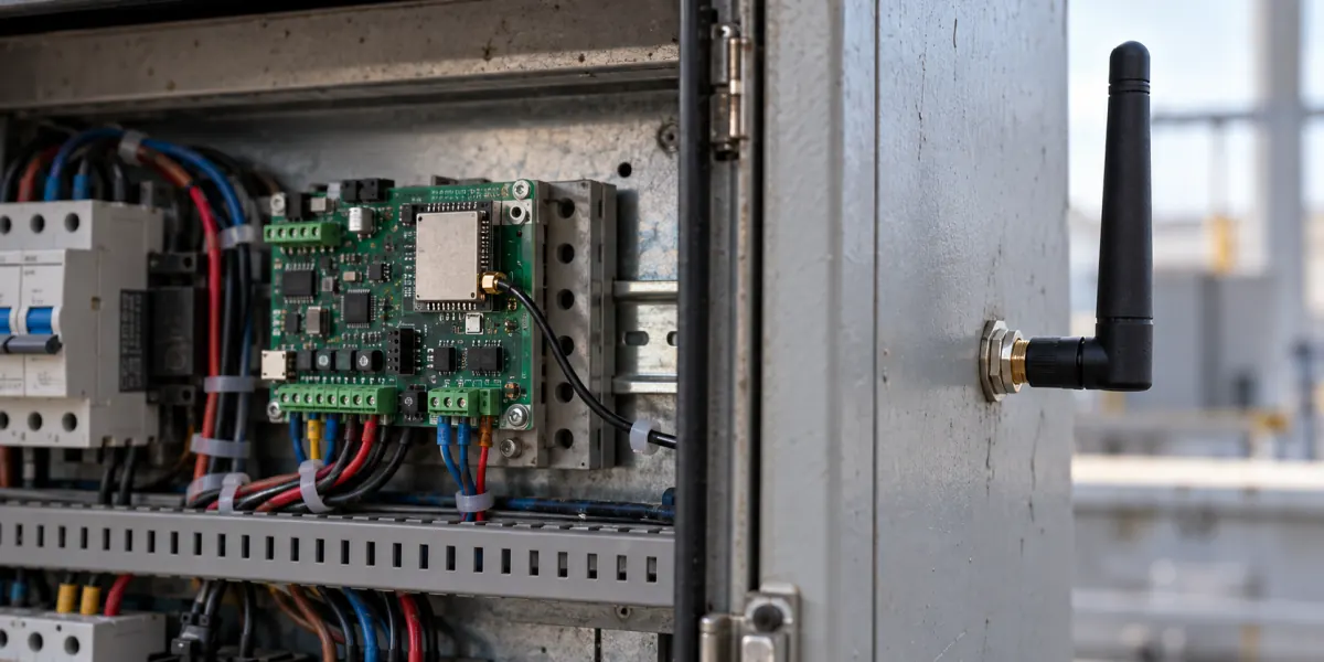
An ESP32 prototype connects reliably on an open bench but drops its Wi-Fi link once the metal cabinet door closes. Replacing the module with an external-antenna version might help, but it is not the first conclusion. First inspect where the antenna sits in the assembled product: the carrier-board edge, nearby metal, cable routing, mounting orientation, and enclosure clearance. Then test an external-antenna assembly if the onboard antenna cannot be given a credible radiating position. Neither a data-sheet gain figure nor one bench RSSI reading settles the choice.
The ESP32-S3-WROOM-1 and WROOM-1U data sheet makes the distinction concrete. WROOM-1 has an onboard PCB antenna; WROOM-1U provides a connector for an external antenna. Choosing the 1U variant changes the complete module and antenna assembly, not just a wire plugged into an otherwise identical board. Verify the exact module dimensions, connector, antenna part, and enclosure drawings before treating the two as interchangeable procurement options.
Inspect the assembled geometry before changing antennas
The PCB-antenna option is worth testing first when the antenna end of the module can sit at the carrier-board edge and the housing leaves useful space around it. That can reduce connector, cable, and assembly variables. It does not establish that the product has adequate coverage. The meaningful question is whether that geometry survives the final housing and installation position, not whether a bare evaluation board can see the access point.
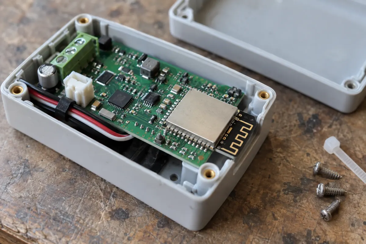
Espressif's ESP32-S3 PCB layout guidance recommends extending the module antenna beyond the baseboard, with its feed point near the board edge. Where that arrangement is impossible, it discusses a board cutout and clearance beneath the antenna. It also recommends at least 15 mm of clearance around the antenna inside the finished housing and testing throughput and communication range in the final product. Treat 15 mm as this vendor's design guidance, not a universal pass/fail dimension for every cabinet.
A metal cabinet changes the mounting question
Put the carrier-board outline and the enclosure cross-section on the same drawing. Mark the antenna region, metal walls, shields, mounting posts, power supply, cable bundles, and the positions in which an installer may actually fix the product. A clearance zone on the PCB layout is not enough if the closed cabinet places a metal wall immediately beyond it. Equally, the phrase “metal enclosure” alone does not prove that every onboard antenna will fail: openings, orientation, and the actual radiation path matter and must be checked in a prototype.
Consider a controller screwed to the inside of a distribution cabinet. If its onboard antenna faces the closed metal door, changing transmit power or comparing open-door RSSI readings does not answer whether the installed controller will maintain its business link. Conversely, a plastic enclosure with the antenna near its outer edge and a feasible baseboard cutout may give the PCB option a straightforward mechanical path. The point is to prioritize the right prototype, not to infer a radio result before measurement.
Clearance drawings are not RF measurements
Changes to the carrier board, nearby high-speed lines, shield, bracket, or cable exit can alter the result after the first layout review. Espressif's hardware guidance also calls out RF routing and interference from adjacent signal paths. Keep the revision of the board and housing with the RF test record; a pass on an earlier prototype should not silently follow a later mechanical change.
Layout review can expose an obvious conflict. Only measurements on the assembled product can establish whether the link meets the product's requirements in its intended network, orientation, and load. No target-product RF measurements are presented here, so this article cannot declare that a particular cabinet will fail with a PCB antenna or pass with an external one.
What the external-antenna option really adds
An external antenna is a useful candidate when the radiating point needs to move out of a metal cavity, when a specified external mounting location is part of the product, or when the carrier board and housing cannot give an onboard antenna a credible position. It moves the radiation point; it does not remove the need to engineer the path between radio and antenna.
The WROOM-1U data sheet describes the external-antenna connector and does not bundle the external antenna with the module. The bill of materials therefore needs a specific antenna, cable or adapter where applicable, and mounting hardware. Mechanical drawings need connector access and cable-bend space. Assembly inspection needs to catch an unseated connector, crushed cable, wrong part, or antenna fixed in the wrong orientation. As Espressif's RF FAQ directs, confirm that the external antenna is correctly connected before powering the module. An antenna with a more attractive nominal gain can still lose its apparent advantage through feedline loss, inconsistent assembly, or poor placement behind the cabinet.
Nominal gain is not a product decision
Espressif's RF FAQ recommends checking external-antenna efficiency, gain, three-dimensional pattern, and whole-device S11; impedance should be close to 50 ohms. The FAQ gives an S11 value no higher than −10 dB as an early design target and directs further attention to efficiency if matching is poor. That is a useful diagnostic target, not a substitute for the product's wireless acceptance criteria or an assurance that a higher-gain antenna works in every intended direction.
Regulatory work is another part of the decision. The FAQ says that reusing the relevant module certification report is conditional on the selected antenna gain not exceeding the gain of the antenna covered by that report. The target market, frequency band, exact antenna, installation, and report scope still require review by the responsible compliance team. A gain comparison alone does not certify the finished device. Avoid approving a last-minute antenna substitution as a purchasing-only change.
Compare complete product options under controlled conditions
An A/B test should compare two assembled product options, not two bare boards with a quick signal-strength snapshot. Hold firmware version, transmit configuration, access point, channel, mounting height, measurement locations, and business traffic as constant as practical. If option B also changes the module variant and antenna location, record those changes explicitly. The A/B result can select the better complete option; it cannot attribute the entire difference to the antenna element alone.
| Keep this condition visible | Why it matters | Evidence to retain |
|---|---|---|
| Cabinet open/closed and product orientation | The door, backplate, and angle change the RF environment | Photos or mechanical drawing, enclosure state, orientation ID |
| Antenna and feedline assembly | Connector, cable length, and mounting position are part of option B | Exact part numbers, cable length, connector and fixing method |
| Network and workload | AP, channel, firmware, or traffic changes can mask antenna differences | AP model, channel, firmware revision, test workload |
| Bidirectional link behavior | One RSSI number cannot describe retries or application availability | RSSI distribution, reconnections, packet loss/retries, throughput or application latency |
Start with both products closed and normally powered, then repeat in the real mounting orientations and with door and cable positions that installers or users can create. For an always-connected controller, include power recovery, network transitions, and coexistence load. Set the duration and pass criteria from the actual duty cycle and service requirement rather than importing a universal number from an article. If remote commands or weak-link alarms matter, capture whether the application recovers after a failed exchange, not just a peak speed-test result.
If transmit looks healthy while receive behavior degrades, increasing transmit power is not a complete diagnosis. The vendor layout guidance describes ways nearby signals can couple into the antenna area; review board routing and interference paths alongside the antenna geometry. If the external assembly is inconsistent, inspect connector seating, cable damage, and mounting orientation. These are fault hypotheses to test on the product, not claims that any particular prototype has already suffered them.
Keep the geometry review and the assembled-product test as separate decisions:

Decide what to prototype, then what to release
Prototype the onboard option first when the module can meet the vendor layout guidance on the carrier board and maintain that clearance after enclosure assembly. It removes external connectors and cable routing from the initial design, but release still depends on the closed-product link meeting the intended workload. “Worth testing first” is not “ready for production.”
Keep the connector-equipped module and a specified external antenna as a candidate when the installed product cannot give the onboard antenna space, or the radiation point must be located outside the metal cavity. Freeze the antenna, feedline, connector, and mounting position together. If neither assembled option meets the requirements, revisit the enclosure, antenna position, or network architecture instead of repeatedly ordering a higher-gain part.
The purchasing decision should name the complete module and antenna part numbers and point to assembly drawings, clearance review, and whole-product test evidence. If you have not yet settled the chip-versus-module question, see the ESP32 SoC versus module selection method. If the S3 family is already chosen but memory and package size remain open, see the ESP32-S3 WROOM versus MINI module comparison. Antenna selection is a later decision: hardware, mechanical, purchasing, and compliance teams should be working from the same assembled-product conditions.