

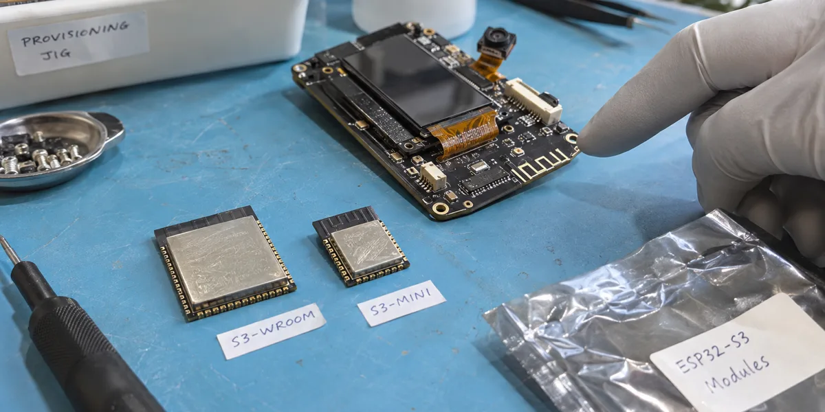
An ESP32-S3 development board running a display, voice, or camera demo does not establish which module belongs on the product PCB. The decision is a complete part number, not simply “an ESP32-S3.” That part number fixes a combination of Flash and PSRAM, affects the signals available at the module pads, and commits the enclosure to an antenna arrangement. Budget the heaviest concurrent workload and map the required pins first. A smaller module or a larger memory number is not, by itself, a product decision.
Compare part numbers, not two broad family names
WROOM-1 and MINI-1 use the ESP32-S3 family, but they are not footprint substitutes. The current Espressif datasheets specify approximately 18.0 × 25.5 mm for the PCB-antenna WROOM-1 and 15.4 × 20.5 mm for the PCB-antenna MINI-1. The external-antenna -1U versions are about 18.0 × 19.2 mm and 15.4 × 15.4 mm respectively. Those are module-body dimensions, not guaranteed occupied area on a finished PCB: antenna clearance, connector access, neighboring metal, and routing still need space. A WROOM development-board schematic cannot simply be relabeled MINI. See the WROOM-1/1U datasheet and MINI-1/1U datasheet.
| Question | MINI-1 / MINI-1U | WROOM-1 / WROOM-1U | Consequence |
|---|---|---|---|
| Module body | 15.4 × 20.5 mm (-1); 15.4 × 15.4 mm (-1U) |
18.0 × 25.5 mm (-1); 18.0 × 19.2 mm (-1U) |
MINI may ease the placement constraint, but neither dimension includes the full antenna and enclosure design. |
| Available Flash/PSRAM combination | N8: 8 MB Flash, no PSRAM. N4R2: 4 MB Flash, 2 MB PSRAM. |
N8: 8 MB Flash, no PSRAM. N8R8: 8 MB Flash, 8 MB PSRAM. Other variants exist. |
The MINI family's “up to 8 MB Flash” and “optional 2 MB PSRAM” do not describe a currently listed 8+2 part. Check the exact suffix before planning OTA or frame buffers. |
| Antenna | -1 has a PCB antenna; -1U takes an external antenna. |
-1 has a PCB antenna; -1U takes an external antenna. |
-1U is a different mechanical and validation path, not a promise of better RF performance. |
This distinction matters when a prototype was built with an 8 MB Flash configuration and subsequently needs PSRAM. The MINI N4R2 offers 2 MB PSRAM but its Flash is 4 MB; it is not an 8 MB Flash module with an added memory option. The corresponding -1U part numbers follow the same memory-combination logic while changing antenna hardware. If the image, asset, and OTA partition budget truly needs 8 MB Flash and the runtime needs more than internal SRAM, compare an appropriate WROOM part rather than assuming a MINI suffix exists. Procurement should list the full manufacturer part number, datasheet revision, and permitted substitutions.
Flash and PSRAM solve different shortages
Flash holds firmware, assets, and upgrade images. PSRAM may hold some large runtime buffers. Increasing Flash does not add camera frame-buffer memory; adding PSRAM does not fix a refresh-timing problem or a partition that cannot hold two firmware images. Internal SRAM, DMA-capable memory, and PSRAM are not interchangeable for every allocation. Record both the peak allocation and the remaining reserve under the intended software configuration. A single idle-memory screenshot on a development board is a weak basis for approving a module.
Translate the product workload into a memory budget
A realistic budget needs the intervals in which operations overlap. A display can be refreshing while Wi-Fi reconnects; a camera can capture while a preview is drawn; a voice device can record while a playback buffer and networking stack are alive. If the team has not measured the worst overlapping interval, treat it as an unresolved validation item rather than silently assuming those tasks are mutually exclusive.
For an RGB565 full-frame buffer, raw pixel storage starts at width × height × 2 bytes. Double buffering doubles that starting figure. It does not include alignment, driver buffers, decode scratch space, GUI objects, network allocations, or fragmentation. A partial-refresh design changes the calculation again. Therefore a formula can reject an obviously undersized configuration, but cannot certify that 2 MB PSRAM is sufficient for an unspecified display. Capture high-water marks with the target resolution, assets, driver mode, and concurrent tasks before freezing a part number.
A display product may be limited by contiguous allocations
Fonts, icons, decoded images, drawing buffers, and an OTA process may compete even on a modest display. MINI N4R2 can be a candidate if its Flash partition budget and runtime allocations both close under the actual product workload. It should not be approved merely because the screen is described as “small.” When an allocation fails, identify its size, required memory capability, and lifetime before trying to move everything to PSRAM. Otherwise a capacity change can hide the symptom while leaving a DMA or timing constraint unresolved.
A camera demo does not cover the product data path
Frame buffers, compression scratch space, and transmission queues may be resident together. A single-frame demo omits sustained capture, connection recovery, storage, and display preview. If the product must retain several frames or run the camera beside a user interface, a WROOM variant with more PSRAM deserves consideration. The actual choice still depends on the sensor, image format, frame size, and supported driver path. No frame-rate, latency, or stability ranking follows from the public module specifications alone; the target board must be measured.
A voice product needs a concurrency map, not just a model size
Recording buffers, a wake-word model, playback, and network packets do not necessarily peak at the same instant. They can overlap during an interaction or an update. Decide the sampling and buffering strategy, whether recording and playback coexist, and whether online and offline modes share memory. A streaming design with a small model may fit a MINI candidate; larger workspaces and concurrent caches may motivate a higher-PSRAM WROOM candidate. Neither statement establishes timing, bandwidth, temperature, or long-running reliability without a repeatable test on the intended hardware.
Pins, antenna, and enclosure can veto the smallest module
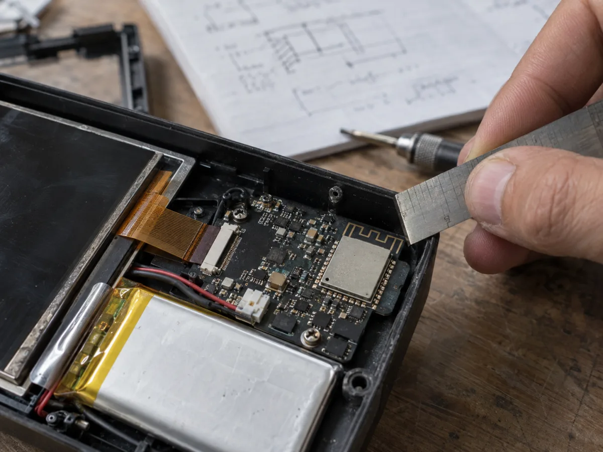
AI-generated enclosure illustration, not a measured target PCB or a source of antenna-clearance dimensions.
A smaller module body does not guarantee a smaller finished PCB. The on-board antenna cannot be crowded by a battery, display flex, ground copper, or metal enclosure simply to save a few millimeters. Espressif's ESP32-S3 PCB layout guidance recommends placing a module's PCB antenna near the board edge and evaluating RF behavior in the end product. An external-antenna -1U variant may be a mechanical answer for some enclosures, but it adds a connector, antenna assembly, and regulatory review. It is not an automatic improvement in range.
The pad and pin plan deserves the same discipline. List the display, camera, microphone, speaker, touch input, USB, debug, and factory-test signals, then check the selected module's exposed pads and boot or memory-related restrictions. A peripheral existing on the ESP32-S3 SoC does not prove that the chosen module and pin assignment can expose every signal simultaneously. Development boards also consume pins for buttons, LEDs, USB, and serial interfaces that might be removed or rearranged in the product. Rework the firmware pin map and manufacturing test plan before layout release.
A release sequence for the module decision
First, describe the actual load: display resolution and buffering mode, camera capture format, audio flow, network concurrency, firmware size, and OTA partitions. Mark which tasks can overlap. Unknown combinations are test risks, not evidence that they never occur.
Second, shortlist complete part numbers from current Espressif tables. For each candidate, record Flash, PSRAM, antenna, dimensions, operating-temperature conditions, and pad layout. Do not treat an unlisted memory combination as an orderable variant. The WROOM R8/R16V variants illustrate why this matters beyond capacity: the datasheet lists a normal ambient range of −40 to 65 °C; enabling PSRAM ECC can raise the upper ambient limit to 85 °C, but reduces usable PSRAM by 1/16. A hot enclosure therefore requires a capacity and temperature check for the specific part and configuration.
Third, validate software and hardware together. Record internal SRAM and PSRAM high-water marks, largest contiguous allocation, and failures during boot, normal operation, worst concurrency, and OTA. In the intended enclosure, test antenna placement, power transients, temperature, and critical interfaces. Keep the firmware version, full module part number, PCB revision, enclosure, and workload with the results so a later engineer can explain why “the same ESP32-S3” behaves differently.
Only then freeze procurement. The BOM needs a complete part number and explicit substitution criteria. Moving to a different PSRAM variant or switching from a PCB antenna to -1U is not a trivial second-source swap: partitions, memory configuration, RF structure, certification material, and factory tests may all need review.
When neither WROOM nor MINI is the right answer yet
If the required signals cannot be exposed together on a candidate module, or the measured worst-case memory reserve is inadequate, comparing body dimensions will not rescue the design. Reduce concurrent load, change the data path, or reassess the processor and system split. Conversely, if a compact module meets the measured product workload, buying a larger PSRAM variant merely for reassurance may add temperature or sourcing constraints without useful capacity.
This is a selection method grounded in published module specifications, not a production result for a particular device. Approval requires the complete part number and measurements from the intended PCB and enclosure—not a screenshot of a running development-board demo.