

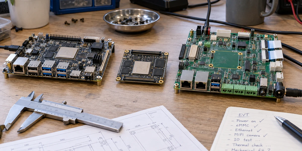
Teams new to Rockchip often compare a development board, a system-on-module, and a carrier board as if they were large, medium, and small versions of the same product. That framing leads to the wrong purchasing question. These boards are not performance tiers; they place engineering responsibility at different boundaries.
Use a development board while the operating system, NPU stack, camera, display, or peripheral path is still uncertain. Use a SoM plus a custom carrier when the processor and memory platform are stable but product I/O, power, mechanics, and compliance still need to be designed. Consider a fully custom mainboard only after volume, size, cost, interfaces, and supply-chain requirements are stable—and only if the team can own DDR, power, BGA, high-speed layout, BSP integration, and long-term maintenance. The cost of choosing too early usually appears after EVT as a board that boots but cannot be frozen for DVT.
The common misconception: these are not three performance tiers
A development board is an expanded validation platform. It exposes many connectors, debug ports, buttons, and power options so engineers can boot a known image, attach peripherals, and isolate faults quickly. Rockchip's RK3588 EVB documentation illustrates this intent with multiple display, storage, camera, networking, and debug interfaces on one board. That breadth reduces the time needed to answer unknown technical questions. It does not imply that every exposed interface belongs in the final product.
A system-on-module, also called a SoM, core board, or compute module, concentrates the SoC, DDR, PMIC, eMMC, and part of the high-speed routing on a reusable module. Radxa's CM5, for example, integrates an RK3588S-class processor, LPDDR4X, optional eMMC, and power management on a 55 × 40 mm module, then exposes signals through board-to-board connectors. Its main value is not that it looks more like a production device. It packages the part of the design that is hardest to repeat and most sensitive to high-speed layout.
A carrier board connects that module to a real product. It owns how 12 V or 24 V enters the system, whether Ethernet needs isolation, whether USB connectors must lock, how MIPI lanes are routed, how fans and RTC are powered, and whether connectors collide with an enclosure. Forlinx's RK3588 platform manual treats carrier power, protection, and power sequencing as separate design responsibilities. A booting SoM and a reliable product power chain are not the same result.
In practical terms, the development board answers whether the technology path can run. The SoM answers which high-complexity compute circuits can be reused. The carrier answers how the device will survive its actual power, peripherals, enclosure, and operating environment.

A development board removes unknowns; it does not represent production hardware
The first job of a PoC is to determine whether the operating system, drivers, media pipeline, NPU toolchain, and critical peripherals can form a working loop. A development board's broad I/O, accessible debug ports, and known images shorten that work. Teams can expose camera compatibility, display timing, model conversion, USB bandwidth, or network throughput problems without debugging a new PCB and power rail at the same time.
A successful PoC only proves that the current sample combination works under the current conditions. The board's regulator margin, connectors, protection, heatsink, cables, and recovery path are usually different from the intended product. Mounting the development board directly inside an enclosure may create excess size, non-locking cables, an unsuitable power inlet, inaccessible recovery buttons, and component revisions outside the team's own BOM control.
A useful exit condition is reached when the software path has been validated and the dominant unknowns have shifted to connectors, power, mechanics, EMC, thermal behavior, and factory test. At that point, more polish on the development board has diminishing value. The product team should turn requirements into a carrier-board interface contract instead of treating the demo as a nearly finished device.
A SoM reduces compute-design risk, not whole-product risk
The SoM route fits a common middle ground. The product needs Rockchip Linux or Android, multimedia, or NPU capability, and it also needs custom Ethernet, serial, CAN, MIPI, audio, or industrial power. Yet the expected volume does not justify the NRE and validation schedule of a fully custom processor board.
In this model, the module supplier owns the SoC, DDR, PMIC, eMMC, and module-level high-speed design, while the product team focuses on the carrier and enclosure. Multiple products can reuse the same compute module while using different I/O carriers. However, matching connectors do not guarantee a drop-in upgrade. Radxa explicitly warns that CM5 must not be installed on a CM3 IO board and documents power-pin and interface differences. Module-generation compatibility must therefore be checked pin by pin, voltage by voltage, and boot path by boot path.
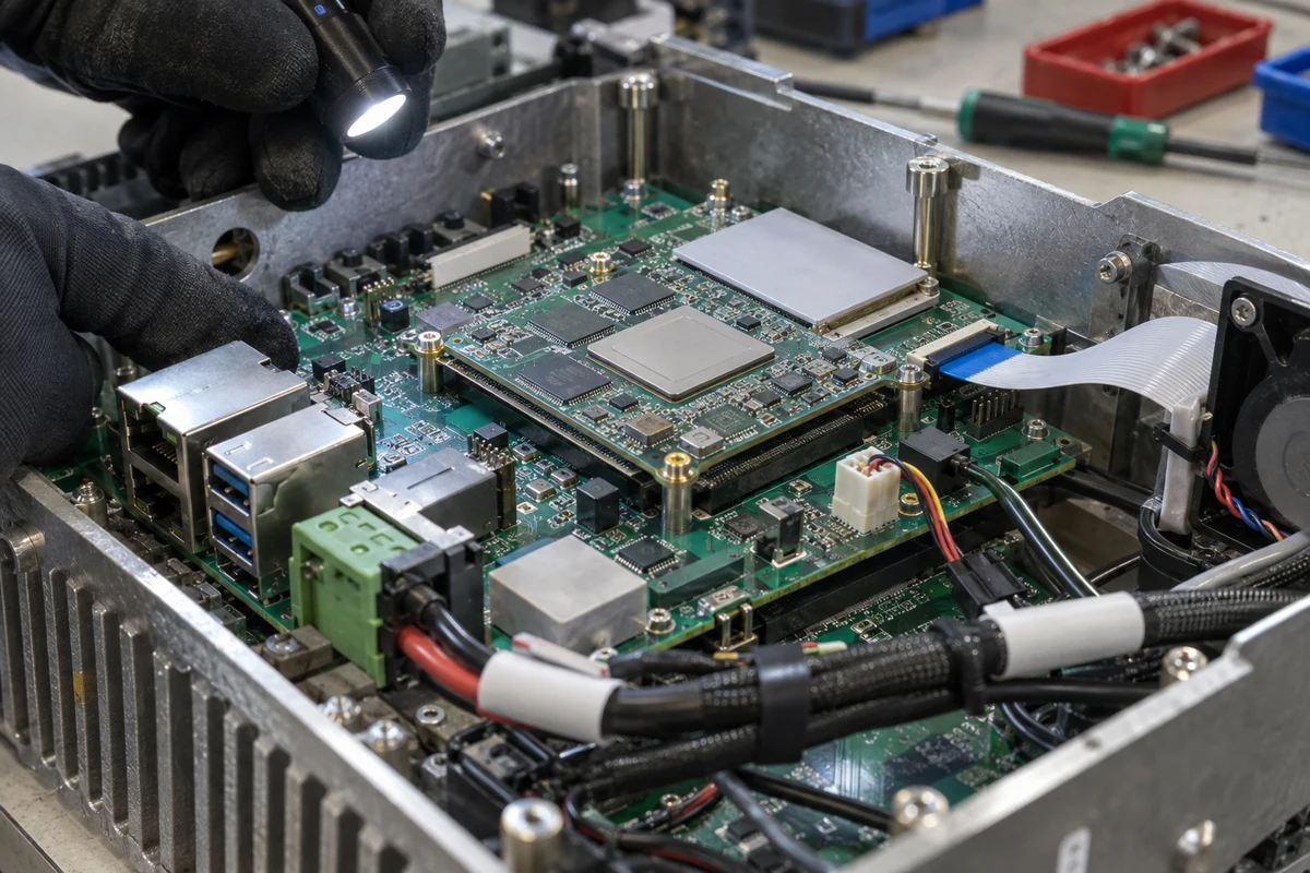
The carrier still owns input protection and power sequencing, connectors and level shifting, ESD and surge handling, antenna clearance, thermal paths, mechanical tolerance, factory test points, and recovery access. If these responsibilities remain open, a booting sample is not sufficient DVT evidence.
Choose the purchase path by lifecycle stage, not unit board price
| Stage | The question that matters now | Better starting point | Evidence needed before moving on |
|---|---|---|---|
| PoC | Can software, models, and critical peripherals close the loop? | Development board | Reproducible image, critical drivers, and interface logs |
| EVT | Can the compute platform and product I/O work on first hardware? | SoM plus first carrier | Schematic review, power sequence, interface smoke tests, and thermal path |
| DVT | Do mechanics, EMC, thermal, reliability, and recovery meet product conditions? | SoM plus frozen carrier, or custom prototype | Environmental, EMC, recovery, and sustained-run records |
| PVT | Can the factory flash, test, trace, and repair consistently? | Production configuration | Fixtures, golden image, serialization, yield, and change control |
| Production | Are cost, supply, and maintenance sustainable? | Frozen BOM with controlled alternatives | AVL, PCN/EOL response, version ownership, and security-update responsibility |
This is not a mandatory migration ladder. A low-volume industrial product may remain on a SoM plus carrier throughout production because slightly higher module cost buys lower design risk and a clearer BSP boundary. A high-volume consumer product may move to a custom mainboard after requirements stabilize, trading one-time NRE for lower BOM cost, smaller size, and greater supply-chain control.
The calculation should cover total risk cost rather than board price alone: electrical design and validation, BSP adaptation, certification reruns, module MOQ, supplier PCNs, field repair, and security updates. At low volume or across many SKUs, the BOM savings of a custom mainboard can easily be consumed by repeated validation and maintenance.
Three choices that commonly create rework
The first is promising a delivery date as soon as the development-board demo works. The image, drivers, and algorithm may run, while product power, mechanics, connector protection, and recovery remain untested. The later the carrier transition happens, the more likely hardware and software failures will arrive in the same iteration and obscure each other's root causes.
The second is buying a SoM by SoC family name alone. Two modules carrying the same RK3588 or RK3568 label can expose different interfaces, power requirements, voltages, eMMC options, wireless combinations, thermal assumptions, and BSP support. A purchase order without a complete part number, RAM/eMMC configuration, module revision, temperature grade, BSP branch, and connector revision does not define a substitutable item.
The third is designing a custom mainboard too early in the name of independence. Rockchip public documentation can describe CPU, NPU, media, and high-speed interface capability. It cannot perform DDR layout, power-integrity review, camera tuning, EMC testing, factory flashing, or multi-year BSP maintenance for the product team. Without the right people and validation budget, full customization does not remove dependencies; it transfers more of them in-house.
Freeze one page of responsibility before requesting quotes
Before issuing an RFQ, product, hardware, software, procurement, and quality owners should agree on a one-page boundary that covers:
- the complete module part number, hardware revision, and allowed alternatives;
- RAM, eMMC, operating-temperature, availability, and lifecycle requirements;
- each high-speed interface, lane map, voltage, and connector revision exposed by the module;
- carrier input power, protection, sequencing, and recovery access;
- ownership for the BSP, kernel, drivers, OTA, and security updates;
- acceptance images and test records for sample, pilot, and production stages; and
- notification, compatibility review, and substitute validation after a PCN or EOL notice.
The purpose is not documentation for its own sake. It keeps the quoted price attached to the same engineering object. Without those fields, suppliers may be pricing materially different deliverables, making the lowest quote impossible to compare.
The shortest reliable summary is this: a development board buys validation speed; a SoM buys reuse of the compute design; a carrier buys product-specific I/O and environmental adaptation; and a custom mainboard buys cost and control after scale justifies the ownership burden. The correct board type follows from the uncertainty the team needs to remove next.
If you are planning a Rockchip SoM, custom carrier, or edge-device production path, our embedded development services and RK3566 lightweight edge gateway guide provide related software, hardware, and operations boundaries.