

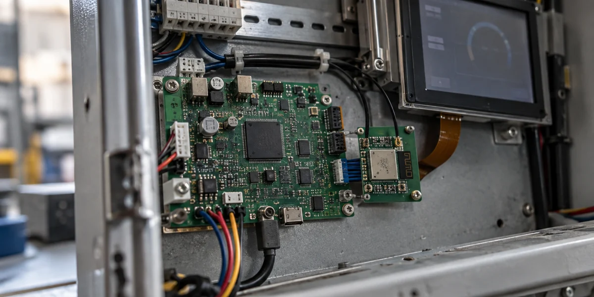
ESP32-P4 does not integrate Wi-Fi or Bluetooth. When a product needs P4's display, camera, or multimedia capabilities as well as wireless connectivity, one officially supported architecture is to use ESP32-C6 as a wireless co-processor. P4 continues to run the application, UI, and TCP/IP stack; C6 performs the actual Wi-Fi and Bluetooth work; SDIO, SPI, or UART connects the two chips.
That is more than attaching a serial Wi-Fi module. Control calls and network data cross the chip boundary. P4 and C6 each run firmware, must establish reset and handshake state during startup, and need a version and update policy that covers both images. A poorly chosen transport can constrain the network path. A demo that connects once, without a dual-firmware lifecycle, merely postpones the hardest failures until system integration or field upgrades.
This article uses Espressif's public documentation to define the architecture and a validation order. It does not contain measurements from a target board, so it makes no project-specific claim about throughput, latency, power, recovery time, or production readiness.
Start with the responsibility boundary between P4 and C6
Espressif's ESP32-P4 Function EV Board guide describes the onboard ESP32-C6-MINI-1 as the Wi-Fi and Bluetooth communication module. That reference design makes the basic split concrete: P4 provides the high-performance MCU, display, imaging, and multimedia side; C6 provides the radios. C6 is neither a standby P4 nor the place where the whole product application must move.
ESP-Hosted divides the inter-chip traffic into two logical paths. The control path carries calls such as scanning, joining an access point, and starting SoftAP from P4 to C6, where the real radio operation happens. The data path bridges network frames from C6 to a network interface on P4. The P4-side lwIP, DHCP, sockets, and application protocols continue to work through that interface.
This split gives debugging a useful order. If the product cannot get online, do not begin with MQTT, HTTP, or certificates. First prove that the P4-C6 transport is established. Then prove that control calls can associate with an access point. Only after that should the team diagnose DHCP and application traffic. If the INIT and capability exchange never completes, cloud-side changes only add noise.
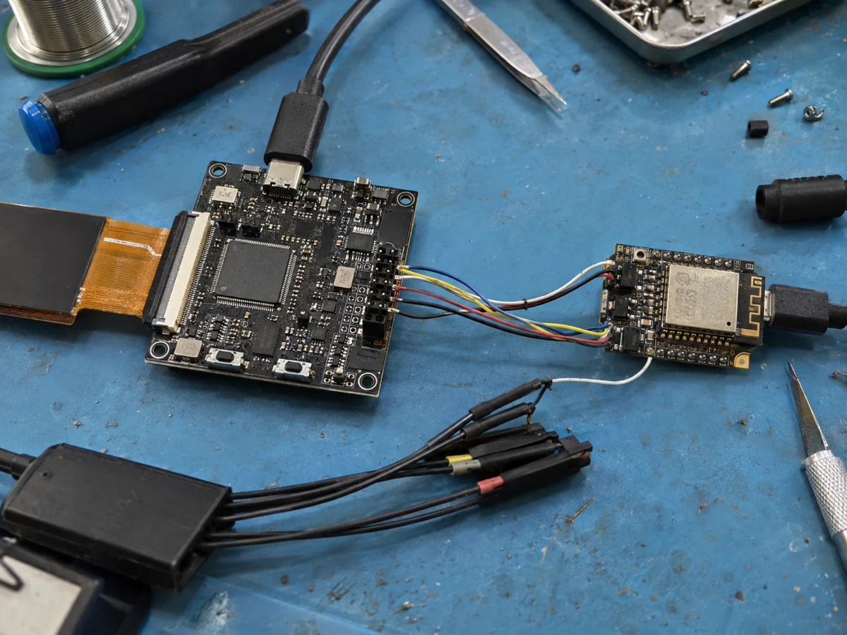
Generated engineering-scene illustration—not an ESP32-P4 Function EV Board and not evidence of a test performed for this article. Validate the target board's pins, power, and signal integrity separately.

SDIO, SPI, or UART: choose for the product, not the demo
The ESP-Hosted-MCU guide supports SDIO, SPI Full-Duplex, SPI Half-Duplex, and UART between an MCU host and an Espressif co-processor. All can establish a hosted link between P4 and C6, but they differ in wiring, board requirements, and the amount of traffic they are meant to carry. Public documentation can support a first elimination round; it cannot supply a throughput promise for a board and workload that have not been tested.
| Transport | What the official guide establishes | A sensible first validation use | Cost to account for |
|---|---|---|---|
| SDIO | It is the highest-throughput option in the guide, and C6 supports it | Products with image, audio/video, larger file, or sustained network traffic, where the PCB can support the bus | More signals, mandatory pull-ups, and a proper PCB for four-bit operation; signal and power integrity require validation |
| SPI Full-Duplex | The guide calls it the easiest and most robust bring-up path; C6 supports it | A first ESP-Hosted design with moderate traffic, where the team wants an observable baseline quickly | Handshake, data-ready, and reset signals are still required; target-load throughput must still be measured |
| SPI Half-Duplex | One-, dual-, and quad-line modes are available, but this is not simply interchangeable with a generic SPI peripheral | Teams that understand the ESP-Hosted SPI-HD implementation and need a more specialized path | Host and co-processor implementations must match; high-speed quad operation belongs on a PCB, not jumper wires |
| UART | It uses the fewest signals, and the guide marks it as the lowest-throughput choice and not for more than 1 Mbit/s | Basic control, low-data prototypes, or a quick proof of the control path | A design can pass a light demo and still fail under real traffic; hosted Wi-Fi and Bluetooth share the link |
Do not copy the development-board pinout blindly
The official guide publishes example mappings for the P4 Function EV Board and C6. A custom board still needs its own pin-mux, power, pull-up, reset, and debug review. SDIO in particular requires external pull-ups on CMD and data lines; the guide also recommends length matching, controlled routing, and power-integrity work for a production PCB. A reference board proves that an architecture exists, not that arbitrary routing will behave the same way.
Both firmware images must also select the same transport, bus width, and pins. A C6 image built for SPI will not negotiate automatically with a P4 image built for SDIO. Store the configuration, board revision, and firmware commit for both sides in one release record. That is much easier to reason about than reconstructing the combination from logs after a field failure.
A practical order for choosing the first bus
If the product clearly carries video, large images, or sustained downloads, evaluate SDIO early and budget its signal, reset, and power work in the schematic. If this is the team's first ESP-Hosted integration and the immediate goal is to prove control, data, and dual-firmware workflows, SPI Full-Duplex provides a lower-friction baseline. UART is suitable for concept proof or genuinely small traffic. It is not a good starting point when the requirement already exceeds the public UART boundary.
The final decision must come from the target workload. Record transport settings, Wi-Fi mode, packet sizes, direction, concurrent UI or camera work, retries, and error counters. A successful ping or DHCP lease proves that basic control and data paths work. It does not prove sustained throughput or acceptable interaction latency for the complete device.
Startup, reset, and two firmware images are the real system boundary
A dual-chip design turns “firmware version” into a tested combination. The P4 host and C6 co-processor use corresponding ESP-Hosted code and configuration. Updating only one side may leave message formats, capabilities, or transport settings incompatible before the business application even starts. A support record should identify the P4 firmware, C6 firmware, ESP-IDF, ESP-Hosted revision, and the combinations that have passed acceptance.
P4 must be able to return C6 to a known state
The official guide requires a host-controlled signal to the co-processor's EN/RST pin and uses it to synchronize startup state. A product cannot assume both chips always power up or reset together. Watchdogs, wake from sleep, brownouts, and partial resets can leave one side holding state from an earlier session. The startup state machine therefore needs an owner for reset, an INIT timeout, a limited retry policy, and a clear degraded state when the wireless co-processor is unavailable.
During bring-up, stop at the first missing checkpoint. Confirm matching transport and GPIO settings, then the INIT and capability exchange, then AP association and an IP address, and only then the real application. If base transport is absent, inspect wiring, pull-ups, power, clocking, and configuration before blaming the access point or backend.
Updating C6 must be part of the product release, not a bench procedure
ESP-Hosted-MCU includes an example in which the host updates the co-processor through the existing transport. The official material also points to a separate UART and serial-flasher path for some designs. Those examples establish that update mechanisms exist. A product still has to define image origin, integrity checks, failure recovery, and version compatibility—and verify that an interrupted C6 update leaves a recoverable device.
A practical release can treat P4 and C6 firmware as two artifacts in one bundle. Record both hashes and the compatible pair. Check preconditions, update the selected side, wait for the transport and network checks to recover, and commit the pair only when the critical application path passes. If the product requires A/B images, rollback, or secure boot, verify those properties on each chip separately. P4-side OTA does not automatically provide equivalent protection for C6.
Where P4 + C6 is a good fit—and where it is unnecessary
P4 + C6 is a strong candidate when the product genuinely needs P4 peripherals or compute: a local vision terminal with MIPI camera and display, a complex LVGL HMI, a multimedia control panel, or a device that benefits from separating UI and imaging work from the radio stack. In those cases, the extra co-processor, bus, and firmware lifecycle purchase a useful combination of capabilities.
If the product is primarily sensing, relay control, or ordinary connectivity and does not need P4's camera, display, or multimedia interfaces, start by evaluating a wireless ESP32-S3, C6, or another single-chip option. One chip removes an inter-chip bus, a co-processor image, and a recovery path. “Newer” or “faster” is not a sufficient reason to select P4; the design should name a local task that a simpler device cannot meet.
The architecture is also a poor fit when the PCB cannot support a reliable SDIO or SPI implementation for the required traffic, or when the team cannot maintain two firmware images. Forcing excessive traffic through UART or relying on manual C6 flashing is a reason to revisit the host or network architecture rather than a workaround to normalize.
Bring these inputs to the schematic review
Before a hardware or development team chooses a bus, provide:
- the UI, camera, audio, or local-inference tasks that run concurrently on P4;
- the peak and sustained Wi-Fi traffic, plus whether Bluetooth runs at the same time;
- GPIOs, reset, debug ports, and PCB resources available for the P4-C6 link;
- startup-time, reconnect, offline, and field-update requirements;
- the release relationship between P4 and C6 images, including signing, rollback, and factory traceability requirements.
That input is enough to choose a useful first SDIO, SPI, or UART validation and to expose whether dual-firmware ownership exceeds the team's support capacity. When the requirement is still only “add Wi-Fi to P4,” the missing design work is usually not an API call. It is bus allocation, reset control, and lifecycle ownership.
For help turning display, camera, and network workloads into pin, firmware, and validation decisions, see our ESP32 development services. If the project is still deciding between a bare SoC and a module, start with the ESP32 SoC versus module selection method. This article turns the P4+C6 architecture into testable questions; it does not replace a target schematic review or prototype test.
References and validation boundary
- ESP32-P4 Series Datasheet
- ESP32-P4 Function EV Board User Guide
- ESP-Hosted-MCU: Getting Started for MCU Host
- ESP-Hosted-MCU: Troubleshooting
- ESP-Hosted-MCU: Host Performs Slave OTA
This article validates only public contracts and examples. It does not measure target-board throughput, latency, power, reconnect behavior, or interrupted updates, and it does not validate a particular antenna, RF, EMC, or factory-flashing design. “Good fit” here means eligible for engineering validation, not production-proven.