

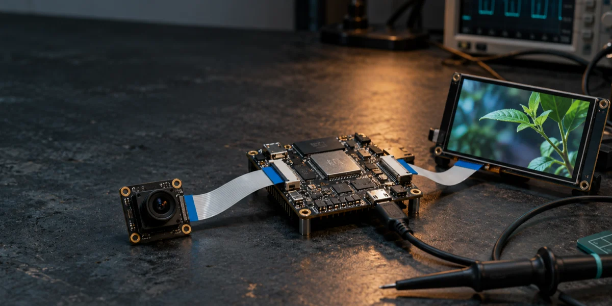
A camera preview that reaches the screen is not yet a reliable camera-to-display design. The critical question is what happens to each completed frame between the sensor and display scanout: its pixel format, the memory it occupies, who may read or write it, and the event that makes it reusable. If an encoder and GUI share the path, those questions matter more than a nominal frame-rate target.
Start with a contract for every boundary. Record the sensor's output mode, what CSI receives, what ISP writes to memory, whether PPA has a specific pixel operation to perform, and which completed buffer the display or encoder consumes. Only then can measured latency, a dropped frame, or a torn image be attributed to a stage. The architecture and API responsibilities below follow public Espressif documentation; they are not performance results from a particular board.
Draw the frame path around memory, not peripheral names
ESP32-P4 has MIPI-CSI, ISP, PPA, JPEG and H.264 hardware, MIPI-DSI, and DMA-capable paths. Their presence does not imply that a frame flows between them without an intermediate write, copy, or queue. The ESP-IDF ISP guide describes an ISP that receives data from a camera controller or system memory and writes processed output to system memory through DMA. That write is an architectural handoff, not a minor implementation detail.

The direct buffer-to-display edge is conditional: output format and display timing must actually be compatible. PPA is a branch for required pixel work, not a mandatory stop between ISP and DSI. Likewise, the GUI arrow is an input to a blend operation; it does not claim that every GUI must be composited into a video frame.
At the central buffer pool, define four events for each frame: allocation, producer completion, consumer completion, and return to the free pool. A frame cannot be recycled just because one task has finished with it if another task, DMA engine, encoder, or display scanout still reads it. This contract often disappears when integration is described only as driver initialization calls.
Freeze the sensor-to-CSI contract before tuning images
A supported CSI format is only the receiver's capability
The ESP32-P4 datasheet lists a two-data-lane MIPI-CSI interface and input formats including RGB888, RGB666, RGB565, YUV422, YUV420, RAW8, RAW10, and RAW12. It does not configure a sensor for you. A valid receiver format says little about the selected sensor register table, lane rate, virtual channel, clocking, or exposure-control sequence.
Keep one reviewable mode record per sensor configuration: active resolution, line and frame lengths, CSI data type and bit depth, lane count and rate, external clock, and exposure and gain controls. If the sensor emits RAW10 but the display ultimately scans RGB565, name the stage that unpacks RAW, performs demosaicing and color processing, and quantizes the result. Otherwise an apparent “CSI works” milestone may conceal a color-order error or line-alignment problem that surfaces only after the display is added.
Use a sensor test pattern, if the sensor provides one, while establishing this boundary. A stable pattern removes scene movement and automatic exposure as competing explanations. Check frame completion and short-frame or line errors before adjusting ISP color parameters. If the pattern itself arrives with unstable rows, downstream image-quality tuning cannot repair the input contract.
CSI's 2.5 V supply belongs in the board bring-up checklist
The ESP-IDF Camera Controller guide calls out a stable 2.5 V supply for the ESP32-P4 CSI peripheral. An internal adjustable LDO can be used, but its configuration and connection must be complete before CSI driver initialization. Treat that as a schematic and power-sequencing prerequisite, not an optional software optimization.
On a custom board, check supply and clock first, then lane continuity and sensor register access, and only then complete image frames. An official development-board example is useful for API ordering, but it does not establish that a different board copied the same electrical path or that a new sensor's mode table is correct.
Make ISP output a useful downstream contract
For RAW input, the ISP can provide the image-processing stages that turn sensor samples into a usable frame: black-level correction, bad-pixel handling, lens-shading correction, Bayer filtering, demosaicing, white balance, and color correction, among others. Which stages to enable and how to tune them depend on the sensor and optics. Driver support for a stage is not a production image-quality calibration.
There is an initialization distinction worth preserving. In the stable v6.1 ISP documentation, using MIPI-CSI or ISP_DVP as the camera controller still requires an ISP processor created with esp_isp_new_processor(), even when ISP image algorithms are not needed. The bypass_isp configuration bypasses the selected algorithm pipeline; it is not a substitute for installing the driver. Recheck these names and requirements against the exact ESP-IDF release used by the product.
Work backward from the consumers
Before selecting an ISP output format, write down each consumer's requirements. The DSI/LCD path has a pixel format, line stride, address-alignment and scanout contract. A PPA operation has supported input and output formats and buffer rules. An encoder has an input format and may hold the frame after the display has moved on. A CPU algorithm may need temporary read access or a separate working copy.
An intermediate format shared by several consumers can remove a conversion, but it is not automatically optimal. Producing RGB for a display and converting it back to YUV for encoding adds memory traffic and queueing. Forcing the GUI to render against an awkward format to save that conversion can shift cost and complexity into composition. Compare complete paths—including memory reads and writes—rather than choosing a format based on one peripheral's advertised capability.
The handoff record should state whether the ISP output is immutable once marked complete. If PPA will modify an output in place where its operation permits it, distinguish that destination from the still-shared source frame. An encoder reading the original frame must not race with a GUI blend writing into it. This is an ownership decision before it is an API choice.
A buffer pool is a latency and correctness policy
Size allocations with stride, not width alone
For an uncompressed frame, begin with frame_bytes = stride_bytes × height. If stride happened to equal width × bytes_per_pixel, RGB565 would need approximately two bytes per pixel and RGB888 approximately three. Real allocations must include line alignment, DMA and driver constraints, and any format-specific planes or padding. The formula is a capacity check, not an FPS prediction.
Count all simultaneously live frames: capture or ISP outputs, PPA inputs and outputs, display framebuffers, GUI draw buffers, and encoder inputs. Then count memory transactions. A full-frame memory-to-memory conversion reads a source and writes a destination; scanout, GUI composition, encoding, and any copy add more traffic. “Does PSRAM fit the bytes?” and “Can the memory system sustain the simultaneous access pattern?” are separate questions requiring target-board measurements.
Single buffering saves capacity but exposes the same memory to producer and consumer contention. Two buffers let a producer work on a next frame while a consumer reads a completed one; they do not establish a safe display swap point. A third buffer can absorb a burst or slow consumer, yet it can leave an old frame waiting in a longer queue. More buffers are not a cure for an unspecified release rule.
Define ownership transitions explicitly
A useful design record names frame states, even if the application uses a different implementation: FREE → WRITING → COMPLETE → IN_USE → FREE. The producer alone owns a WRITING buffer. After its DMA completion and any memory-visibility work required by the configured memory region, it publishes a COMPLETE frame. Each consumer acquires a read claim; the pool recycles the frame only after the last claim is released and display scanout no longer references it.
That last condition matters when preview and H.264 encoding fork from one source. Reference counting, explicit per-consumer acknowledgments, or another equivalent mechanism can implement it. A frame should not be returned on “display finished” if encoding is still reading, nor on “encoder submitted” if encoding has only queued asynchronous work. Define whether the completion event means accepted, processed, or no longer reading memory.
Cache consistency belongs at the same transition. If the chosen CPU, DMA, and external-memory arrangement requires cache clean, invalidate, or barriers, perform the operation appropriate to the handoff direction before publishing the buffer or reusing it. Do not apply a generic cache recipe without checking current ESP-IDF memory and DMA requirements. When faults appear only with cache enabled, PSRAM placement, or higher concurrent load, first test visibility and premature reuse before labeling the symptom “insufficient bandwidth.”
For a low-latency preview, an explicit policy may discard an expired completed frame and show the newest complete one. For per-frame analysis or archival, silently overwriting work is incorrect; backpressure, reduced input rate, or a documented degraded mode is needed. Log which policy fired. A display may scan the last complete frame again when its refresh rate exceeds capture rate; it must not scan a frame still under construction.
Give PPA a named pixel job
The ESP-IDF PPA guide describes scale/rotate/mirror, blending, and filling. PPA can move a required pixel operation out of general CPU code, but it still reads memory and writes a result. Its value depends on the transformation and resulting buffer traffic, not the mere fact that it is hardware acceleration.
Use it when sensor orientation differs from display orientation, when the preview window must be resized, or when a video frame and GUI surface must be blended. The PPA guide specifies separate input and output picture buffers for a scale/rotate/mirror operation; blending has different aliasing rules. Those distinctions matter when sizing a pool and deciding whether the original frame remains available to an encoder. Validate formats, block dimensions, offsets, alignment, and completion semantics for the operation actually selected.
If sensor output already matches the display's size and orientation, a whole-frame PPA pass may be unnecessary. For GUI overlays, compare two architectures: compose UI into the video frame, or let the display path manage video and UI separately where driver and hardware support that mode. Composition yields one final frame but may require substantial pixel work after each UI change. Separate layers or partial updates can avoid rewriting video pixels, but require compatible display features and careful synchronization. A claim of reduced CPU use alone does not settle the end-to-end tradeoff.
Split display and encoding into different consumer contracts
The display needs a complete frame available at the scanout deadline. The MIPI-DSI LCD example shows driver-managed framebuffer use and an LVGL draw-buffer arrangement in PSRAM. The MIPI-CSI–ISP–DSI example is a public reference for wiring modules together. Neither example proves a particular panel timing, sensor mode, UI load, or product memory layout.
Changing an address or writing a framebuffer while the display scans it can put two generations of pixels on one screen. The swap therefore needs a defined synchronization point and a buffer the producer will not overwrite. The right mechanism depends on panel timing, DSI driver behavior, and framebuffer mode; allocating two buffers without specifying the swap event is not a tearing test.
An H.264 encoder has a different deadline and output responsibilities: accepted input format, ordered frames, rate control, encoded-output buffers, and downstream storage or network consumption. Hardware encoding does not make its input lifetime zero. If preview and encoding share a source, the slow branch extends that source's lifetime. If encoding receives a separate copy, budget the extra allocation, read/write traffic, and delay. The display may prioritize freshness while the encoder requires continuity; one unbounded queue cannot satisfy both goals by accident.
Choose the contract that matches the product
| Requirement or observation | Design response | Cost or boundary to verify |
|---|---|---|
| Lowest useful preview age | Keep the newest complete frame; document when older frames are dropped | Measure capture-to-scanout age and drop reasons, not just average FPS |
| Every frame must be analyzed or retained | Preserve per-frame ownership and apply backpressure or an explicit degraded mode | Queue growth, capture pressure, and recovery behavior |
| Rotation, scaling, or video/UI blend is required | Put the named operation on a PPA branch after checking formats and buffer rules | Extra memory transaction, destination buffer, and completion handoff |
| Preview and H.264 share a frame | Hold the source until both consumers have stopped reading | Encoder-induced pool starvation and display freshness |
| Camera format already matches display needs | Evaluate the direct completed-buffer route | DSI compatibility, scanout lifetime, and safe swap timing |
This table is a decision aid, not a promise that all options can run together at a given resolution. Datasheet capabilities, reference examples, and measured end-to-end product behavior are different evidence classes.
Diagnose the first boundary that corrupts a frame
Similar screen artifacts can have unrelated causes. A color cast can originate in sensor output order, ISP color processing, RGB/BGR convention, or display interpretation. Repeating horizontal displacement points toward line length, stride, or starting address. An occasional old image suggests queue age, a missed swap, or incorrect return to the free pool. Adjusting the last module until the screen looks acceptable can hide an upstream error.
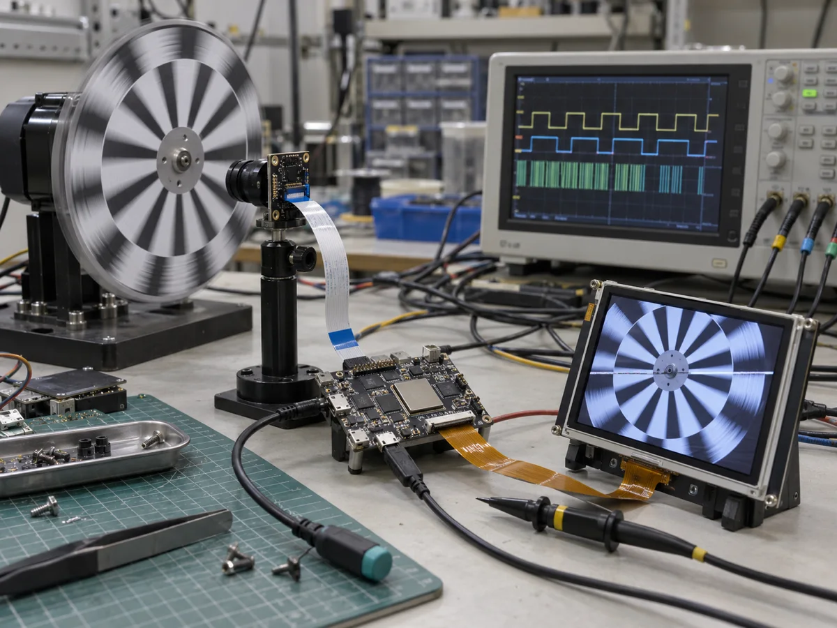
AI-generated bring-up scene for orientation, not a photograph of the target board or evidence of measured performance.
Place a comparable observation at each boundary. With a sensor test pattern, record CSI completion and error counters. At ISP memory output, inspect fixed rows and pixel positions along with recorded width, height, format, and stride. Save a small set of pre- and post-PPA frames to see whether rotation, scale, or blend changed unintended areas. At DSI, correlate the chosen framebuffer address with swap and refresh events. Preserve the failing frame's ID, buffer address, stage, and event order so an intermittent failure can be traced to one handoff.
Do not treat visual correctness as latency evidence. Timestamp capture completion, ISP completion, PPA completion where used, display swap/refresh, and encoder completion where used. Record buffer-pool high-water mark, queue depth, dropped-frame reason, buffer location, and cache/DMA properties alongside those timestamps. A system can show an attractive average FPS while displaying increasingly stale frames or occasionally reusing a buffer too early.
Bring up the shortest observable route first
- Control the sensor. Read its identity, fix one mode table, and save resolution, data type, lane configuration, clock, and power assumptions.
- Prove CSI capture. Prefer a known test pattern. Log frame completion, short frames, line errors, and DMA status before adding a complete UI.
- Fix ISP output. Start with unnecessary automatic adjustments disabled. Verify dimensions, stride, pixel order, and color; enable image-quality functions one by one.
- Prove display ownership. With no GUI or encoder, identify producer completion, display acquisition, the swap event, and release event. Use timestamps, GPIO markers, or a logic analyzer where appropriate.
- Add one PPA operation at a time. First test a required scale or rotation, then any GUI blend. Record its destination buffer, completion, and incremental memory traffic.
- Add optional encoding or network consumption last. Exercise a deliberately slow consumer and observe queue high-water marks, drops or backpressure, and recovery.
At every step, retain ESP-IDF version, board and chip revision, sensor and panel part numbers, input/output formats and resolutions, buffer count, and memory placement. Without those identities, a later measurement cannot be compared fairly. The references here span stable v6.1 ISP documentation, v6.0 PPA documentation, latest Camera Controller documentation, and master-branch examples. They establish public responsibilities, not a tested single-SDK integration matrix.
Know when this is the wrong single-chip architecture
ESP32-P4 can fit products where MCU-level control, a camera input, local image processing, and an HMI must be tightly integrated. Its peripheral list alone is not a selection argument. A product needing complex multi-stream media handling, mature container support, heavy GPU composition, or large vision models may be better served by a Linux SoC and its media stack. At the other extreme, an occasional still image and simple display may not justify the power, routing, driver, and verification work of the full CSI–ISP–PPA–DSI path.
Sensor and panel ecosystems also matter. Missing stable drivers, timing data, or supply continuity cannot be fixed by the MCU's interface specification. If requirements simultaneously insist on no dropped frames, minimal preview delay, continuous encoding, and a complex GUI, first allocate explicit memory, power, thermal, and degradation budgets. Those goals may compete for the same buffers and bandwidth.
Before product review, assemble one stage-by-stage table covering format, resolution, stride, buffer size and count, memory region, DMA/cache attributes, producer, consumer, and release event. Then measure capture-to-display and capture-to-encode behavior under the fixed target workload. Public documentation supports the module responsibilities and validation method presented here; it does not establish frame rate, end-to-end latency, absence of tearing, memory bandwidth, power, temperature, or long-run stability on your hardware. Those are acceptance results to produce, not conclusions to import from an example.