

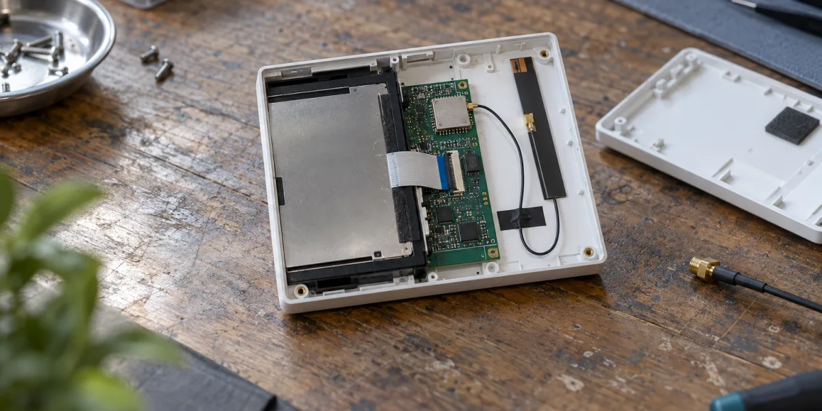
Three labels often share one cell in a module-selection spreadsheet: Wi-Fi 6, 5 GHz, and external antenna. They describe different things. The first is a radio-standard capability, the second determines which networks the product can join, and the third changes how the RF path is placed inside the enclosure. If a customer network is 5 GHz-only, a 2.4 GHz Wi-Fi 6 module cannot join it. If a metal panel blocks the antenna, adding 5 GHz support will not fix the layout. Separating these requirements before selecting a part number prevents a surprising amount of redesign.
Tuya's published module specifications make the distinction concrete. T7-U-IPEX lists both 2.4 and 5 GHz plus 802.11ax. WBR2D is dual-band but lists standards through 802.11n. T5-E1-IPEX lists 802.11ax but only at 2.4 GHz. These are three different answers to a product requirement, not simply three price/performance tiers. See the official T7-U-IPEX, WBR2D, and T5-E1-IPEX datasheets.
Put the target network in the requirements table
Start with the network the device is expected to use. Does the installation site expose a 5 GHz-only SSID? Are 2.4 and 5 GHz advertised under the same name? Is the AP managed by the customer, with a channel or security policy the product cannot change? A 5 GHz requirement may eliminate a 2.4 GHz-only candidate immediately. Conversely, a continuously powered gateway that exchanges only modest control traffic is not automatically a dual-band product merely because it is called a gateway.
Write those network constraints as testable inputs. Include the expected SSIDs, AP families, installation positions, enclosure material, and sales regions. A datasheet establishes the module's advertised band and mode support. It cannot establish that your finished device will connect reliably behind a metal cabinet door or through a particular customer's router configuration.
Check channels and operating modes by market
The T7-U-IPEX datasheet lists 5 GHz channels and also distinguishes regional 2.4 GHz channel availability. It notes a restriction involving UNII-2A/2C for certain STA/AP combinations. Do not turn the full channel list in a generic datasheet into a promise that every channel is usable in every country and mode. Check the actual product firmware, configured country, target AP, and intended provisioning mode together. A gateway sold in several regions needs a region-by-region release decision, not merely a “dual-band” checkbox. Tuya T7-U-IPEX datasheet
If the market list is still open, keep the corresponding regulatory and router assumptions open too. The module's radio table is an input to that work; it is not approval for the final enclosure and antenna combination.
What would 802.11ax change in this product?
Wi-Fi 6 refers to 802.11ax support, while dual-band refers to operation across 2.4 and 5 GHz. T7-U-IPEX lists a/b/g/n/ac/ax across both bands; T5-E1-IPEX lists b/g/n/ax at 2.4 GHz; WBR2D lists a/b/g/n across two bands. A comparison sheet needs separate columns for band, standard, antenna, and provisioning. Otherwise a dual-band Wi-Fi 4 candidate can be mistaken for a Wi-Fi 6 candidate, or a 2.4 GHz Wi-Fi 6 candidate can be mistaken for a 5 GHz solution. T7-U-IPEX, T5-E1-IPEX, WBR2D
Make ax a hard requirement only when a customer network policy requires it or a specific product workload depends on a published ax capability that the target AP also supports. It is an unsupported leap to infer better installed coverage, throughput, latency, or coexistence from the standard name alone. The RF figures in a module datasheet come from stated test conditions. Once the module sits behind a display, beside a switching supply, or inside a metal body, the product has a different set of variables.
“High-throughput device” is not specific enough either. A camera's usable uplink may be constrained by its encoder, protocol, power design, AP congestion, or antenna placement. A touch controller may use the network mainly for commands and updates. Establish the actual traffic and AP environment before paying for a radio capability that might not move the bottleneck. This article contains no same-enclosure, same-router measurements and therefore does not rank the modules by speed.
Put three candidates back into the enclosure
| Candidate | Published Wi-Fi capability | Antenna form | Question to settle before selection |
|---|---|---|---|
| T7-U-IPEX | 2.4/5 GHz, including 802.11ax | External dual-band FPC-IPEX antenna | Is there a validated antenna position and feed path, and a regional channel test plan? |
| WBR2D | 2.4/5 GHz, through 802.11n | Onboard PCB antenna | Is dual-band sufficient without ax, and is the board/enclosure clearance acceptable? |
| T5-E1-IPEX | 2.4 GHz, including 802.11ax | External-antenna variant | Is 5 GHz truly unnecessary, and can the board accept this footprint and interface? |
This table reduces the candidate set; it does not certify any candidate for production. T7-U-IPEX gives the mechanical team some freedom to position a separate antenna, while adding a connector, feed, assembly, and antenna-variation checks. WBR2D avoids that external RF assembly but makes the module's PCB antenna position and clearance more consequential. The T5-E1-IPEX datasheet explicitly says it is not pin-to-pin compatible with T5-E1. A family name is therefore not a substitute for a footprint review. T7-U-IPEX, WBR2D, T5-E1-IPEX
An external antenna needs an actual place to live
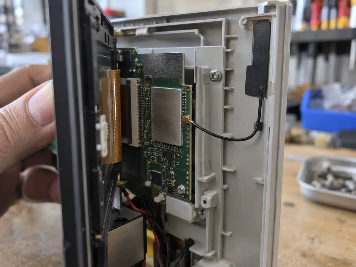
AI-generated placement illustration, not a photograph, dimensional drawing, or RF test result for any specific Tuya module.
Tuya specifies an external dual-band antenna connection for T7-U-IPEX and provides guidance about separation from metal. In a control panel crowded with a screen, shield, power supply, and cable loom, antenna placement cannot be left until the end of prototype testing. The enclosure drawing should identify its mounting point, cable bend and routing, nearby metal, assembly tolerances, and plausible user interaction. The datasheet gives constraints; matching, radiated behavior, and weak-signal performance need tests on the target product. T7-U-IPEX datasheet
An onboard PCB antenna is not free of placement work. If WBR2D is pressed against metal or a noisy power section, the board design and finished enclosure still have to be checked against its hardware guidance. The decision is about where you place RF design freedom and validation responsibility, not about a universally superior antenna type.
Power and host interfaces move with the radio choice
The WLAN column is only one part of integration. Verify supply range and transient behavior, UART and GPIO availability, boot and reset paths, debug access, memory, and the intended firmware role. An appliance with an existing MCU may care most about the serial protocol and which processor owns the state machine. A design that runs more application code on the module has different memory and peripheral constraints. A suitable wireless specification does not imply that an existing PCB, jig, or MCU protocol can stay unchanged.
Changing to a different dual-band package can trigger PCB work, firmware changes, RF retuning, production-test updates, and fresh certification review. Without a supplier quote or project-hours record, those costs should not be expressed as a precise number. They should still be visible in the decision log, with owners and release conditions for each work item.
Provisioning is a separate product path
The T7-U-IPEX datasheet lists Bluetooth and AP provisioning modes. WBR2D lists SmartConfig and AP modes. Tuya's generic protocol documentation explains how Bluetooth, AP, and EZ paths pass router credentials, but the mode available in a specific product depends on its module, firmware, product configuration, and app. T7-U-IPEX, WBR2D, Tuya pairing mechanisms
It is easy to see “dual-band” in a module brochure and assume the current phone onboarding flow will also work unchanged with a 5 GHz SSID. Device discovery, credential transfer, association with the target network, and later reprovisioning are separate steps. Test them with the target phone and app versions, the actual router/SSID configuration, and the product firmware. When onboarding fails, record the failed step rather than labelling the entire problem a 5 GHz fault.
A useful first matrix covers a shared-name dual-band SSID, separate SSIDs, the customer's 5 GHz-only case where applicable, relevant security settings, and reconnect after a router change. It should reflect real sales environments, not attempt to claim universal compatibility with every router. Bringing the app team into module selection is cheaper than discovering a provisioning mismatch after the board is frozen.
Candidate paths and stop conditions
If 5 GHz is required but ax is not, WBR2D is a dual-band candidate when its onboard-antenna layout can be accommodated. Its published radio specification does not make the product a Wi-Fi 6 upgrade. If both 5 GHz and ax are required and there is room for an external dual-band antenna, T7-U-IPEX deserves evaluation. If the product remains on 2.4 GHz but calls for ax or other T5-E1-IPEX resources, that module belongs on the shortlist; it cannot satisfy a 5 GHz requirement.
There is also a valid decision to keep the current radio. When the observed issue is antenna clearance, enclosure attenuation, or an onboarding mismatch, and no network or workload requirement calls for a new band or standard, address the confirmed cause first. A new module adds board, firmware, manufacturing, and certification work. It is a poor substitute for diagnosing where a connection actually fails.
These are shortlist rules, not test results. Before freezing a part number, fix the sales region, AP/phone baseline, enclosure, antenna approach, and firmware configuration. If one of those inputs is unknown, retaining two candidates for prototype validation is more defensible than declaring a single winner from a specification table.
Evidence needed before release
Keep four kinds of records with the part-number decision. First, retain the RF and mechanical design: antenna placement, clearance, feed or PCB-antenna keep-out, and weak-signal/coexistence checks in the target enclosure and mounting position. Record router, firmware, and test conditions; a screenshot showing full signal bars is not a coverage test. Second, retain the provisioning trace across discovery, credential transfer, association, and recovery for the actual app, phones, and SSIDs. A failed case should identify its stage.
Third, record the board and manufacturing interfaces: supply behavior, UART/GPIO mapping, reset and recovery, flashing/authorization, and test-jig changes. This is essential for replacements, where an apparently similar family name may hide different pins. Fourth, record the market decision: module certificates, the chosen antenna/enclosure combination, sales region, sample configuration, and the certification laboratory's scope. Tuya distinguishes module approvals from regulatory approval of a finished product. A certified module does not automatically authorize a finished device after its antenna and enclosure change. Tuya product certification
Hand these records to purchasing alongside the candidate part number. Purchasing can confirm the actual supply option and region-specific variant, while hardware, firmware, and app owners can sign off on the interfaces they must test. The analysis above uses publicly available Tuya documentation as read in October 2026. It does not include chamber tests, router-compatibility results, throughput, quotations, or production outcomes for a particular product. Those final decisions belong to the device and markets you will actually ship.