

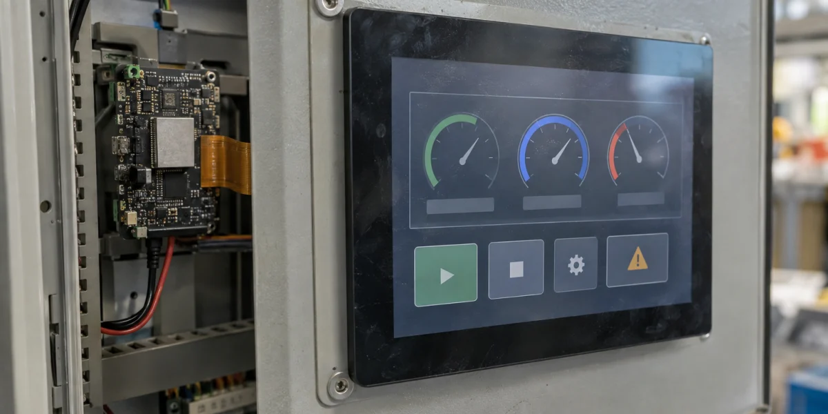
An 800 × 480 panel in RGB565 needs 768,000 bytes for one uncompressed frame. Two panel frames alone consume about 1.46 MiB, before LVGL draw buffers, fonts, decoded images, rotation workspaces, or other tasks enter the budget. A display demo that boots on an ESP32-P4 therefore says little about the memory available to the finished HMI. The first useful design step is to name every buffer, its owner, and the point at which it is read or written. Only then can a team make a defensible choice between one, two, or three panel frames. Espressif's LVGL Adapter guide treats interface, frame count, tearing mode, and draw-buffer height as separate decisions.
This is a design and validation guide based on public APIs. It does not report frame rate, touch latency, tearing improvement, or sustained behavior from a particular board. Those outcomes require a specified panel, PSRAM configuration, firmware version, workload, and measurement record.
Put the three kinds of memory on different lines
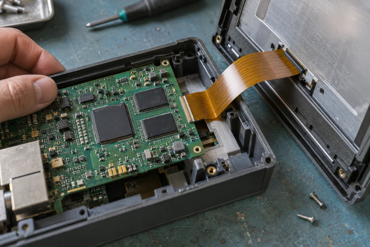
Generated hardware-scene illustration, not a board photograph or benchmark result.
Teams often call all display-related storage “video memory,” then discover that enabling a feature added an entire frame they did not budget. The panel frame buffer holds pixels read by the display path. In MIPI-DSI Video mode, pixel data streams from a host-side frame buffer; the ESP-IDF RGB driver likewise reads a configured internal-memory or PSRAM frame. An LVGL draw buffer serves a different purpose: LVGL renders an invalidated region into it. Depending on the render mode, it may be smaller than the screen. Rotation, scaling, blending, and color conversion may need another input or output workspace. Some adapter modes share addresses between layers; others do not. A memory worksheet must reflect the actual selected path rather than adding or merging buffers based on similar names. See the MIPI-DSI driver, RGB driver, and PPA driver.
Trace one update before selecting a frame count
During a partial update, LVGL renders the invalidated area into a draw buffer. An adapter or application flush then transfers those pixels into a writable panel frame while the display engine may still be scanning a different frame—or the very same one. If the scan and write overlap without a clear ownership rule, the image can contain portions from different update cycles. A second frame makes separation possible, but it does not by itself synchronize frame switching, keep unchanged regions consistent, or map touch coordinates after rotation. Espressif explicitly calls out synchronization between two PSRAM frames in its RGB double-buffer description.
With esp_lvgl_adapter, select RGB or MIPI-DSI first. Then pick a supported tearing-avoidance mode and pass the count returned by esp_lv_adapter_get_required_frame_buffer_count() into the panel configuration. DOUBLE_DIRECT, DOUBLE_FULL, TRIPLE_PARTIAL, and TRIPLE_FULL address different update-area and rotation needs at different memory costs. Three frames are not a universal “smoothness” setting. The adapter also rejects nonzero rotation with the RGB/DSI NONE mode. If the project composes LVGL, esp_lcd, and PPA itself rather than using the adapter, it owns the equivalent flush, frame-lifetime, and synchronization contract. The adapter's behavior must not be assumed to appear automatically in a custom port. Adapter mode rules
Work backward from resolution and pixel format
The first-pass panel-frame calculation is horizontal pixels × vertical pixels × bytes per pixel. RGB565 uses two bytes per pixel; RGB888 uses three. In the table, MiB means 1,048,576 bytes. These numbers are raw pixel storage only. They exclude row-stride alignment, driver allocation, caches, icons, fonts, decoding, heap fragmentation, and conversion workspaces.
| Assumed panel format | One raw frame | Two raw frames | Three raw frames |
|---|---|---|---|
| 800 × 480, RGB565 | 0.73 MiB | 1.46 MiB | 2.20 MiB |
| 1024 × 600, RGB565 | 1.17 MiB | 2.34 MiB | 3.52 MiB |
| 1024 × 600, RGB888 | 1.76 MiB | 3.52 MiB | 5.27 MiB |
The table is especially useful for ruling out an impossible starting configuration. Two 1024 × 600 RGB888 frames contain 3,686,400 raw bytes in total, about 3.52 MiB. If the total allocatable PSRAM remaining after camera, network, and UI resources is below that amount, a configuration switch cannot make the pair fit; revisit color format, resolution, frame count, or concurrency. If the frames are separately allocated, each allocation also needs an available contiguous block of at least 1,843,200 bytes, plus actual alignment overhead. The 3.52 MiB total is not a single-allocation contiguous-block requirement. The reverse inference is invalid: enough capacity does not prove enough throughput. Display scanning, CPU rendering, PPA reads and writes, and other clients can contend for external memory. The RGB driver documents the tradeoff between saving internal RAM and sharing PSRAM access with EDMA; the DSI driver requires the actual panel timing and pixel format, not only the frame's byte count. RGB buffer modes, MIPI-DSI configuration
Budget the LVGL draw buffers separately. A hypothetical 800-pixel-wide, 50-line RGB565 partial buffer contains 80,000 raw bytes, about 78 KiB; two such buffers double that component. The 50-line height is the adapter documentation's default example for RGB and DSI, not a product-wide recommendation. A taller buffer can reduce the number of flushes while using more RAM. A shorter one reduces allocation but can add calls and copies. The actual allocation depends on LVGL color format, memory capability, adapter mode, and whether draw and panel buffers share storage. Confirm the worksheet against runtime allocations; do not mistake the table for a predicted heap_caps_get_free_size() reading. Adapter buffer-height guidance
Put every buffer in one ownership worksheet
The following is an illustrative allocation, not a verified adapter mode or a board measurement: 800 × 480 RGB565, two distinct panel frames, one 50-line partial draw buffer, no rotation, and no PPA call. Raw pixel storage is 2 × 800 × 480 × 2 = 1,536,000 bytes for the panel frames plus 800 × 50 × 2 = 80,000 bytes for drawing: 1,616,000 bytes, about 1.54 MiB. It excludes driver allocations, alignment, assets, and concurrent peaks. A selected adapter mode might share physical storage between the draw and panel buffers, or allocate them separately. Do not order PSRAM from this example alone.
| Buffer | Raw size / assumed location | Writer and reader | Handoff and synchronization check |
|---|---|---|---|
| Panel frame A | 768,000 bytes / PSRAM | Refresh path writes when available; display DMA reads when scanning | Transfer at the driver- or adapter-defined frame switch; establish who synchronizes CPU/PPA writes before DMA reads |
| Panel frame B | 768,000 bytes / PSRAM | Alternates with A as writable and displayed frame; do not overwrite during scan | Also verify how unchanged regions persist and when the frame becomes writable again |
| LVGL partial draw buffer | 80,000 bytes / actual memory region to verify | LVGL writes; flush or adapter reads | Reuse only after flush completion; if physically shared with a panel frame, count that allocation only once |
| PPA SRM workspace | Zero in this baseline; budget separately if enabled | PPA reads input and writes a distinct output | Check input/output non-overlap and the CPU/DMA handoff for the chosen operation |
Adding one separate, full-size RGB565 SRM output workspace is a conservative scenario, not a claim about an adapter's actual allocations. It would bring the illustrative raw total to 1,616,000 + 768,000 = 2,384,000 bytes, about 2.27 MiB. Fill in the real addresses, largest allocatable blocks, alignment overhead, and any shared physical storage before adding rows to get a product budget. Even when two uses share one allocation, record their separate ownership intervals; subtracting bytes alone does not make concurrent writes safe.
PSRAM adds a correctness contract, not just capacity
When a display DMA path reads pixels and a CPU or PPA path writes them, address reachability, alignment, and cache coherency can determine whether the correct image appears. Espressif's ESP32-P4 memory-synchronization documentation describes both directions of the problem: a CPU write may remain in cache when DMA reads external memory, or a CPU read may observe stale cached data after DMA has changed memory. If an application manages these buffers below the adapter, identify who allocates them, which DMA engine can reach them, what alignment applies, and where synchronization belongs. esp_cache_msync() is an official mechanism, but sprinkling a call before and after every flush is not a substitute for a defined read/write lifetime. ESP32-P4 memory synchronization
The largest contiguous allocatable block matters more than a headline PSRAM capacity. Fonts, icon decoding, networking, and other components can consume or fragment memory before a new screen or keyboard opens. A successful one-frame boot does not establish that later UI transitions can allocate the next working buffer. Record free memory, the largest block, and peak usage at boot, after entering the most demanding view, and during a transition. If the product also uses a camera, list camera frames separately. Our ESP32-P4 camera-to-display pipeline article follows video acquisition and transformation; this article concentrates on HMI rendering and panel-frame ownership.
RGB and MIPI-DSI are different refresh contracts
The ESP-IDF RGB driver offers internal-memory single-frame, PSRAM single-frame, PSRAM double-frame, and bounce-buffer modes. A single frame uses less storage but can still be scanned while an update is written. Double buffering separates the currently displayed frame from a writable one, at the cost of another full frame and a rule for keeping unchanged content consistent. Bounce buffering is not free double buffering: the documented RGB path combines a PSRAM main frame with two smaller internal buffers and line-level movement between CPU and DMA. It can tolerate some short bandwidth spikes, but uses more CPU and depends on external-cache availability. A working RGB recipe should not be copied without review to a DSI panel. RGB LCD operating modes
In MIPI-DSI Video mode, the host streams pixels from frame memory. Panel-control commands on the DBI path and video data on the DPI path have different jobs. The lane configuration, rate, color format, pixel clock, blanking intervals, and DPHY power must agree with the selected panel. esp_lcd_dpi_panel_get_frame_buffer() exposes addresses allocated by the driver. Before handing those addresses to LVGL or PPA, define when each may be written, when a completed frame becomes visible, and whether an adapter already owns that transaction. The ESP-IDF DSI driver exposes a DMA2D draw-bitmap hook and a custom-hook route for PPA operations; the existence of a hook does not mean rotation and compositing automatically use it. MIPI-DSI LCD driver
Diagnose symptoms by layer rather than increasing clocks immediately. A panel that never displays an image calls for power, initialization commands, lane wiring, and timing checks before LVGL buffer tuning. Misaligned rows or wrong colors call for a review of stride, region coordinates, pixel format, byte order, and DMA alignment. Tearing only during animation points toward the relationship among invalidated regions, writable frames, scanned frames, and VSYNC or transfer-completion callbacks. Espressif's LCD FAQ distinguishes insufficient PSRAM fetch bandwidth from lane-rate and timing mismatch; one blue-screen symptom should not be labeled “LVGL is too slow” without evidence.
Give PPA a specific pixel operation
The ESP32-P4 PPA can accelerate scaling, rotation, mirroring, blending, and filling. It can take a specific pixel transform away from a software path. It cannot decide which LVGL objects need redraw, create PSRAM bandwidth, or settle cache and frame-switch ownership on behalf of the application. The PPA SRM operation requires different input and output picture buffers. A design that budgets only the pre-rotation frame but no output workspace can fail before measuring a single frame. Blend has different conditions for buffer reuse; check the API for the operation actually used rather than assuming all PPA transactions have the same memory rules. PPA driver contract
A 90° or 270° orientation also changes width and height, touch mapping, invalidated areas, and intermediate-buffer calculations. In some adapter rotation and tearing-avoidance modes, Espressif requires three frame buffers. That requirement belongs to the documented mode; it does not imply that every custom driver needs exactly three or that any particular panel will benefit. Recalculate memory for the final orientation and pixel format before enabling rotation. If the panel controller can deliver the desired orientation without a full-frame transform, verify that route before accepting another frame-sized copy. Adapter frame-count and rotation rules
Move from a demo to a testable product configuration
Freeze the board inputs and assign memory ownership
Start with the panel's resolution, orientation, pixel format, interface, refresh requirement, and touch controller. Add the PSRAM part and capacity plus concurrent network, camera, audio, and logging work. There is no meaningful “best frame count” while these inputs are still moving. Lock the ESP-IDF, LVGL, and adapter versions used by the target firmware; macros and mode behavior can change between releases. A snippet from one release is not a cross-version product contract.
If wireless work is delegated to an ESP32-C6 companion, include P4–C6 data exchange and concurrent load among those inputs. Our ESP32-P4 + C6 companion architecture explains that responsibility boundary; it does not replace a PSRAM peak measurement on this device.
Then write a buffer-ownership worksheet: allocator, size, internal or external location, CPU/PPA/DMA permissions, handoff point, cache-synchronization owner, and release path for every buffer. Apply num_fbs, buffer_height, and color format to the capacity calculation, then add measured peak costs for fonts, textures, conversion, and concurrent features. If allocation fails, find the frame-sized consumer and any alignment overhead first. Enlarging an abstract “PSRAM size” setting does not explain which allocation was wrong or whether a full-size buffer could have been a region buffer.
Compare legal configurations and preserve a fallback
On the same target board, compare at least two valid configurations: for example, partial updates with one panel frame against an adapter-supported two-frame DOUBLE_DIRECT path at the same pixel format, or a two-frame path against a rotation mode that needs three. Change one variable at a time. Capture free and largest-contiguous memory, LVGL render time, flush or transfer time, actual displayed frame rate, CPU load, touch-to-visible-change latency, and the exact content that tears if tearing occurs. A mostly static demo screen is a weak workload. Include charts, popups, animation, language switching, and concurrent network activity relevant to the product. Public documentation gives the candidate modes; it cannot supply these board-level results.
Keep a low-complexity known-good display configuration so a failed optimization has a rollback. If enabling PPA produces color displacement, return to the untransformed path while comparing input and output buffers, format, stride, and alignment. If a second frame reduces throughput, inspect extra whole-frame copies and PSRAM contention before assuming a third frame will help. If an RGB bounce-buffer configuration fails during OTA or flash writes, check that mode's documented dependence on external cache. These are targeted investigations, not claims that this article reproduced those faults. RGB bounce-buffer limitations
Product sign-off should be more precise than “the UI feels smooth.” Name the board and panel revision, firmware and adapter versions, exact screen and concurrent load, test duration, sampling method, and blocking failures. Memory staying within bounds, acceptable interaction, no reproducible tearing under the chosen workload, and a workable fallback are separate conditions. This article offers a way to design that evidence. It cannot assert an FPS target, latency, or long-term stability for any device until those measurements exist.
Where this budget does not apply
This memory and refresh discussion is aimed at RGB or MIPI-DSI HMI paths on ESP32-P4. It must not be copied unchanged to SPI, QSPI, or I80 screens. Espressif's adapter groups those as OTHER interfaces and lists only NONE for its tearing-avoidance mode; their transfer path and any panel-local memory need their own analysis. Even on RGB or DSI, the panel timing, PSRAM part, power design, and concurrent load set the actual limit. “The adapter exposes a mode” and “our product passed in that mode” are different statements. Adapter interface support