

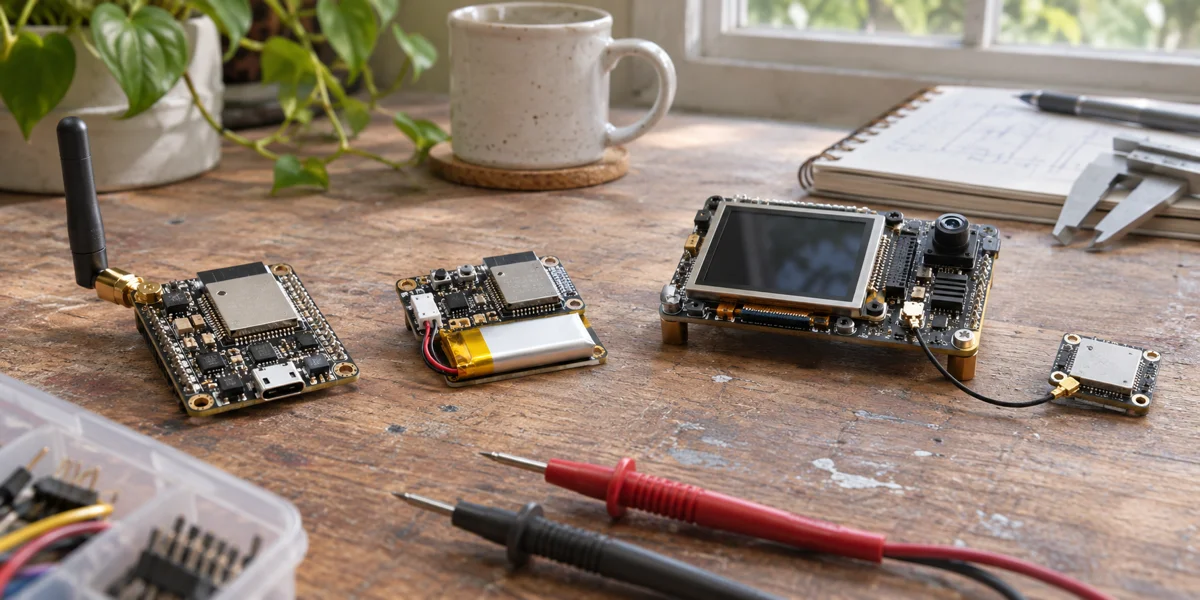
A Wi-Fi controller, a battery-powered Thread sensor, a voice terminal, and a camera-equipped display do not share one sensible ESP32 shortlist. Start with the jobs that must survive a network outage, the radio each device actually needs, and the processing load that stays on the device. Only then decide whether one SoC can own the product or whether processing and connectivity should be split.
Two boundaries immediately eliminate common mistakes. ESP32-H2 can serve an IEEE 802.15.4 node, but it does not provide native Wi-Fi. ESP32-P4 offers substantial display and camera interfaces, but it too has no native Wi-Fi. A product that needs either chip and Wi-Fi must show the additional connectivity path on its system diagram. The decisions below are based on Espressif's published chip and SDK documentation; they are not measurements of power, audio accuracy, or production reliability.
Give each chip a job before comparing part numbers
The question “Which ESP32 is the most powerful?” is usually too broad to authorize a schematic. Ask instead: Which component joins the network? Which one preserves local control? Where do display buffers and voice models run? What happens when a second radio protocol becomes necessary?
| Product responsibility | Initial candidate | Critical condition |
|---|---|---|
| Ordinary 2.4 GHz Wi-Fi control | ESP32-C3 or another suitable Wi-Fi SoC | Verify pins, memory, secure update space, and board-level power against the real workload |
| Wi-Fi plus an 802.15.4 roadmap | ESP32-C6 and related candidates | Define whether the product is an end device, bridge, or border router before selecting a stack |
| Battery Thread or Zigbee node | ESP32-H2 | It has no native Wi-Fi; a gateway or a second connectivity device must provide remote access |
| Local voice and modest interaction | ESP32-S3 as a candidate | Separate wake word, command recognition, synthesis, and cloud conversation requirements |
| Demanding display or camera terminal | ESP32-P4 for processing | It has no native Wi-Fi; design a separate connectivity path if Wi-Fi is mandatory |
This is a responsibility map, not a final bill of materials. A specific module's antenna, flash, PSRAM, temperature rating, certification, and availability can overturn a family-level recommendation. ESP32-C5 and other newer candidates may also matter when the network requirement changes. Freeze an exact module part number before procurement.
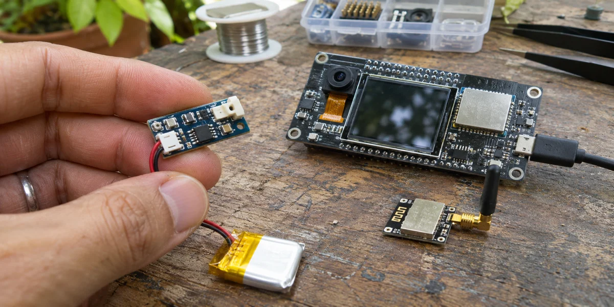
Generated illustrative photograph, not an Espressif reference-board photo or evidence of a specific chip's performance.
The three costs of a one-chip design
First is persistent resource use: the network stack, application state, credentials, and OTA layout consume memory and storage before the visible feature runs. A display framebuffer or voice model adds to that demand. Second is the critical path: a busy network must not unexpectedly disable a local button or safety function. Third is migration: adding Thread later can mean a new PCB, SDK work, and certification work, not merely a firmware flag.
One chip is attractive when it meets the required radio, memory, I/O, and failure behavior with verified margin. A two-chip architecture adds interfaces and firmware coordination, but it can be the clearer design when no single candidate can honestly own both processing and connectivity. Component count alone is a poor proxy for total product cost.
Four product situations, four different starting points
A connected controller: eliminate unnecessary features first
Imagine a controller with a few sensors, buttons, and actuators. It joins a 2.4 GHz Wi-Fi network and must continue local operation during an internet outage. It has no camera, large display, or local voice model. ESP32-C3 is a reasonable baseline candidate: Espressif's ESP-IDF documentation identifies its Wi-Fi, Bluetooth LE, and single-core RISC-V platform. The next question is whether the target board has enough I/O, flash, RAM, security capacity, and OTA space—not whether another family has a more impressive marketing label.
If the product later needs 5 GHz Wi-Fi or different peripherals, revisit the candidate list around that new constraint. If Thread or Zigbee becomes a direct device requirement, compare an 802.15.4-capable family such as ESP32-C6. But “supports Matter” does not define whether the product is an endpoint, bridge, or border router. That role determines the software and interoperability tests.
A battery node: H2 has a deliberately narrower role
Imagine a door sensor or environmental node that communicates over Thread or Zigbee and relies on a gateway for internet access. ESP32-H2's Bluetooth LE and IEEE 802.15.4 capabilities fit this job. Its lack of native Wi-Fi is not a defect if the system already has a gateway; it is a system boundary that must be explicit in the product architecture.
If the requirement changes to “every battery node connects to Wi-Fi directly,” this is no longer the same design. Recalculate the energy budget, wake frequency, connection time, and remote-access path rather than pretending H2 gained Wi-Fi. A family name cannot establish battery life: regulator losses, sensor supply, module choice, and wake behavior need measurement on the target board.
A voice terminal: wake word is not conversation
Imagine a tabletop terminal with a wake word, short offline commands, local control, and cloud-assisted conversation. ESP32-S3 may be a useful integrated audio and connectivity candidate. But “voice support” contains distinct functions: wake-word detection, command recognition, speech output, and open-ended dialogue have different model, memory, language, and network requirements. Espressif ESP-SR's supported functions and targets also change by version. Fix the component release and audio hardware, then test the intended language, noise environment, and latency on the real board.
If a cloud model handles conversation, decide which commands remain available offline, whether audio leaves the device, and where echo cancellation runs. If a large screen, camera, and complex animation are added, a processing chip plus a connectivity chip may become more appropriate. Define audio ownership, UI ownership, failure recovery, and coordinated updates before drawing the board. No accuracy or end-to-end latency claim follows from a supported feature list alone.
A display and vision terminal: leave room for P4's connectivity partner
Imagine a camera-equipped terminal with a comparatively demanding interface and mandatory Wi-Fi. Espressif's ESP32-P4 documentation describes interfaces including MIPI, USB, SDIO, and Ethernet. P4 can take the processing and display role. Its Wi-Fi expansion documentation explicitly requires another path for Wi-Fi, such as another ESP32. The processing side and connectivity side should therefore appear on the first system diagram, not as a late PCB addition.
That split creates four interface decisions: how application data crosses the chips, how a connectivity fault is recovered, how two firmware versions are upgraded compatibly, and how production support diagnoses failures. If the product merely shows a few status values, the added complexity may not pay for itself. A simpler single-chip design deserves evaluation before committing to P4.
Ask for a failure demonstration, not only an online demo. When the wireless side restarts, can the display still show trustworthy local state? If a processor update fails, can the connectivity side be identified and recovered? These are validation questions, not claims that this article has tested a P4 board.
Constraints that a feature matrix hides
Protocol capability is not a verified product role
ESP32-C6 combines Wi-Fi, Bluetooth LE, and IEEE 802.15.4 capability. That does not prove a particular board, SDK version, and Matter or Thread role have been validated together. Once the role is defined, inspect the matching Espressif examples, stack versions, radio coexistence, certification scope, and OTA path. Until those combinations are tested, they remain architecture candidates.
Turn “supports both radios” into a test that can fail: keep Thread traffic running on the target board while Wi-Fi carries the expected application load, then force a Wi-Fi disconnect and reconnect. Measure lost Thread messages, control-response time, and recovery time against the product's limits. Two separate single-radio demos do not establish that both roles work concurrently in the product. If the combined path misses the limits, narrow the promised behavior or split the responsibilities. This is an acceptance method, not a measured C6 result.
A host and wireless coprocessor need a failure contract
With ESP32-P4 plus a wireless ESP32—or another host paired with an ESP32 connectivity device—the inter-chip link is not a transparent cable. Specify which side owns Wi-Fi credentials, reconnection, time synchronization, and recovery after version mismatch. Espressif's P4 Wi-Fi expansion and ESP-Hosted materials help identify supported communication approaches. They do not establish throughput or robustness for an untested board. Procurement and firmware teams should work from the same responsibility diagram.
SDK versions belong in the selection record
Record the intended ESP-IDF, ESP-SR, and connectivity-component versions at selection time. A latest documentation page can move; an example building successfully does not show that an existing production board can migrate without changes. For a shipped device, list driver changes, flash layout, NVS data, encryption keys, bootloader behavior, factory tools, and rollback requirements before choosing a new family. If the benefit is only that the new part looks more modern, keeping the existing validated design may be the better business choice.
A selection meeting can end with a test plan
- State which functions must survive an internet outage and which networks are mandatory rather than hypothetical.
- Draw the responsibility map: sensing, control, audio, graphics, and public connectivity. Show H2's and P4's missing native Wi-Fi explicitly.
- Compare exact modules, not family names: pins, flash, PSRAM, supply, antenna and certification, temperature range, and availability.
- Freeze software versions and test the hardest path on target hardware: offline control and OTA for the controller; actual sleep behavior for a battery node; language, noise, and latency for voice; graphics, camera, and connectivity concurrency for the display terminal.
- Reject candidates with a documented reason. Turn a candidate architecture into a BOM only after its critical assumptions survive those tests.
Do not use this map as a purchase order when regional certification, board area, power architecture, security separation, or existing firmware assets impose a stricter constraint. A development board with PSRAM cannot prove that a no-PSRAM module runs the same voice model; a reference board's radio performance cannot stand in for a custom PCB. Lock the full module part number and hardware revision, then verify the design.
The meeting should leave two falsifiable assumptions, not just a preferred-chip table: first, that the one-chip candidate has enough free memory and update space for the intended workload; second, that a split design's link, restart behavior, and coordinated firmware upgrade can be diagnosed and recovered by the product team. Assign a target board, software version, acceptance threshold, and owner to each. If the first assumption fails, consider splitting the roles. If the second fails, P4's display capability alone does not justify shipping a two-chip product.
The existing C3/S3/C6 firmware comparison answers a narrower single-chip question. The existing P4/S3 HMI comparison focuses on screen and vision boundaries. This article's distinct answer is how to assign roles inside a product, and when a single SoC should give way to a processor plus a connectivity device.
Sources and limits
- Espressif ESP-IDF: ESP32-C3 Get Started documents the C3 platform and radios.
- Espressif ESP-IDF: ESP32-H2 About documents H2's Bluetooth LE and IEEE 802.15.4 role.
- Espressif ESP-IDF: ESP32-P4 Get Started and Wi-Fi Expansion describe P4 interfaces and its external Wi-Fi path.
- Espressif ESP32-C6 hardware overview describes C6 radios; freeze the document version for a real project.
- Espressif ESP-SR provides voice-component releases and supported targets.
There is no target schematic, BOM, power trace, concurrency result, speech-quality test, customer project, or production validation behind this article. The four situations are design hypotheses for narrowing candidates, not measured rankings or case studies.