

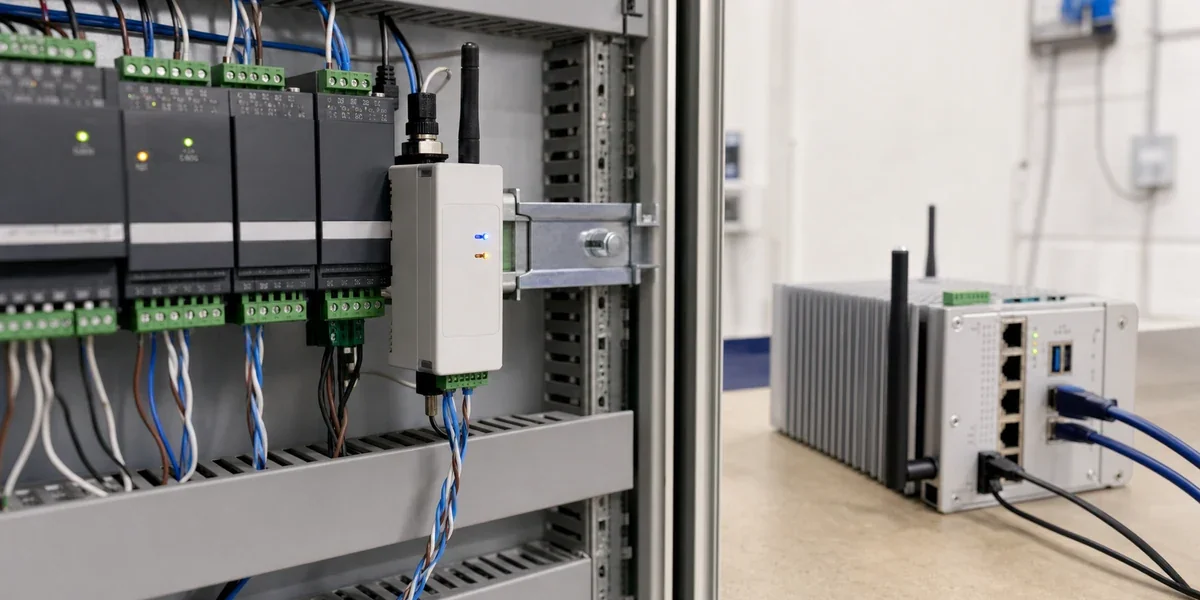
Before ordering converters for an RS485 equipment networking project, establish whether the target equipment exposes usable data, how the site can carry it and who needs to act on it. A physical connection alone cannot answer those questions. Missing protocol details or an unclear operational goal can leave a connected device with no trustworthy platform information.
Record unknown items as unknown, together with the person or supplier who can resolve them. Do not borrow settings from a similar-looking controller and present them as confirmed inputs. This preparation applies to existing refrigeration controllers, meters and other serial equipment being considered for a controlled networking pilot.
An RS485 port does not establish protocol compatibility
TI's RS-485 Design Guide defines an electrical interface. It does not define the register map, field units or permitted commands of a particular machine. Obtain information for the actual model and firmware version, including read permissions, scaling and invalid-value rules. A response that parses into the wrong temperature or counter value is not a reliable operational input.
A serial converter provides a communication path; it cannot supply missing equipment documentation or decide what an operator should do after an alarm. Early discovery should establish whether data can be read consistently, how the local link will be installed, where the information belongs and who owns the response.
Existing stable Wi-Fi may be suitable for a small installation. A ZigBee serial port converter is another candidate when the equipment distribution, wiring constraints and gateway design support it. Choose a transport after identifying the required data flow, rather than treating a converter as a complete integration plan.
Ten project inputs to collect
| Input | Record | Why it matters |
|---|---|---|
| Equipment identity | Manufacturer, model, controller version and quantity | Defines the compatibility scope |
| Physical interface | RS485 or RS232, terminals and isolation requirements | Determines electrical connection work |
| Serial settings | Baud rate, data bits, parity and stop bits | Establishes a reproducible communication setup |
| Application protocol | Protocol document, register map or authorized samples | Defines interpretation and adaptation work |
| Device addresses | Assigned addresses and possible duplicates | Supports a valid polling arrangement |
| Required information | Measurements, states, faults and read/write scope | Defines the platform data model |
| Data timing | Required freshness and expected response behavior | Informs polling and capacity assessment |
| Site conditions | Positions, metal obstructions and network availability | Constrains local transport and gateway placement |
| Power and installation | Supply, cabinet space and maintenance windows | Bounds installation work |
| Operational ownership | Alarm recipients, permissions and response expectations | Makes monitoring actionable |
These inputs support a discovery conversation; they are not proof that every item has already passed validation. When protocol information is incomplete, select one representative device for authorized read-only work before committing to a batch of hardware.
Match the investigation to the operational goal
Remote status and alarms
For monitoring, identify the exact fields that should trigger an action and the person who will respond. Set the required data age from the business risk, device response and available link capacity. There is no single minutes-based sampling interval that suits all temperature, energy and equipment-state applications. A delayed value that is acceptable for a daily report may be unsuitable for an operational alarm.
Agree how the platform will distinguish equipment faults from missing data. A device that stops responding should not remain visibly healthy because its last recorded value was within limits. The receiving system needs the relevant timestamps and a quality state, along with a defined response to stale information.
Shared operations across several devices
Add equipment identities, site grouping, permissions, alarm ownership and history to the scope. Confirm whether an existing HMI or PLC already acts as the serial master. The Modbus serial specification V1.02 allows one master at a time on the same bus. A new collector may require a coordinated access path rather than independent parallel polling.
Changing the transport from a cable segment to a wireless link does not fix competing masters, duplicate addresses or inconsistent field meanings. Name the component that will decode the protocol and the party responsible for maintaining model-specific mappings. Converter firmware and gateway capabilities should be confirmed for the proposed delivery.
Remote control
Separate low-frequency parameter changes from time-critical or safety-related control. Keep protective interlocks and continuous control with the appropriate local controller. For any permitted remote configuration, agree authorization, command limits, confirmation and audit records before enabling writes. A monitoring-only pilot need not expose write operations to demonstrate that useful data can be collected.
Resolve unknowns with one read-only sample
Capture an authorized request and response together with the device-display value, settings and time. Check how the raw field becomes the platform value and what happens when a response is missing or invalid. If documentation or permission is unavailable, resolve that boundary with the equipment owner or vendor; do not discover an unknown protocol by trying undocumented write commands.

The sequence describes proposed discovery work, not acceptance results from an existing project. Prepare model lists, interface photographs, protocol documents, equipment locations, intended data fields and sample quantities for the equipment networking inquiry. A sample device and permitted response records make the remaining technical unknowns more concrete.
Define what a successful pilot must demonstrate
Choose one equipment model and a representative site area. Agree in advance what records will establish correct values, communication-loss indication and delivery of alarms to the responsible person. Where safe and authorized, exercise loss and restoration of connectivity, including the expected treatment of buffered or delayed information.
Reuse the resulting template only for matching controller versions and installation assumptions. A different device model or a different site network needs renewed confirmation. The outcome of discovery is a defensible pilot scope and a list of resolved inputs, not an untested promise that all equipment is ready for rollout.
Sources and scope
Protocol boundaries are based on TI SLLA272D, revised May 2021, and Modbus serial V1.02. The discovery and acceptance steps are engineering recommendations. No controller compatibility measurements, customer-site tests, range guarantees or savings claims are supplied by these public sources.